Device and Process for Removing Contaminants from a Fluid Using Electromagnetic Energy

a technology of electromagnetic energy and fluid, which is applied in the direction of separation processes, electric/magnetic/electromagnetic heating, evaporation, etc., can solve the problems of large investment, unsuitable surface disposal, and inconvenient reinjection of fluid, so as to reduce environmental and regulatory permitting time, reduce equipment size, and reduce scaling formation

Inactive Publication Date: 2013-09-05
SHUMWAY SCOTT
View PDF3 Cites 5 Cited by
  • Summary
  • Abstract
  • Description
  • Claims
  • Application Information

AI Technical Summary

Benefits of technology

[0010]1. The use of electrical energy to supply the heat eliminates the need for fuel handling, boilers, emissions, ash, and other problems associated with combustion.
[0011]2. Use of electrical energy to heat the fluid reduces environmental and regulatory permitting time.
[0012]3. The use of electrical energy instead of combustion greatly reduces the size of the equipment, thereby allowing it to be portable.
[0013]4. Scaling formation is greatly reduced in the apparatus where energy is added to the solution for the purposes of raising the temperature to a point where the solution is able to boil or beyond as the design might dictate, however the energy added does not include a heat exchanger surface and is instead added by subjecting the bulk fluid to microwave radiation.
[0014]5. System is easily scalable, whereby additional capacity can be added such that additional flow can be accommodated as it is required.

Problems solved by technology

Disposal of the produced water is a problem where for various environmental reasons reinjection of the fluid is not advisable or even allowed.
Because of the high salinity, the solutions are toxic to aquatic creatures and are therefore not suitable for surface disposal.
The industrial plants that can process fluids of this nature are often called Zero Liquid Discharge (ZLD) processing plants, and require a large investment.
In many areas of the country, the availability of legal injection boreholes is limited and requires long hauling distances of large volumes of fluid and is therefore not cost effective and impractical.
ZLD processing plants are generally regional and the operation of these plants is very costly and complex.
The permitting, design, and construction of these systems requires significant investment and the timeline from concept to production is long.

Method used


Image

  • Device and Process for Removing Contaminants from a Fluid Using Electromagnetic Energy
  • Device and Process for Removing Contaminants from a Fluid Using Electromagnetic Energy
  • Device and Process for Removing Contaminants from a Fluid Using Electromagnetic Energy

Examples


Embodiment Construction

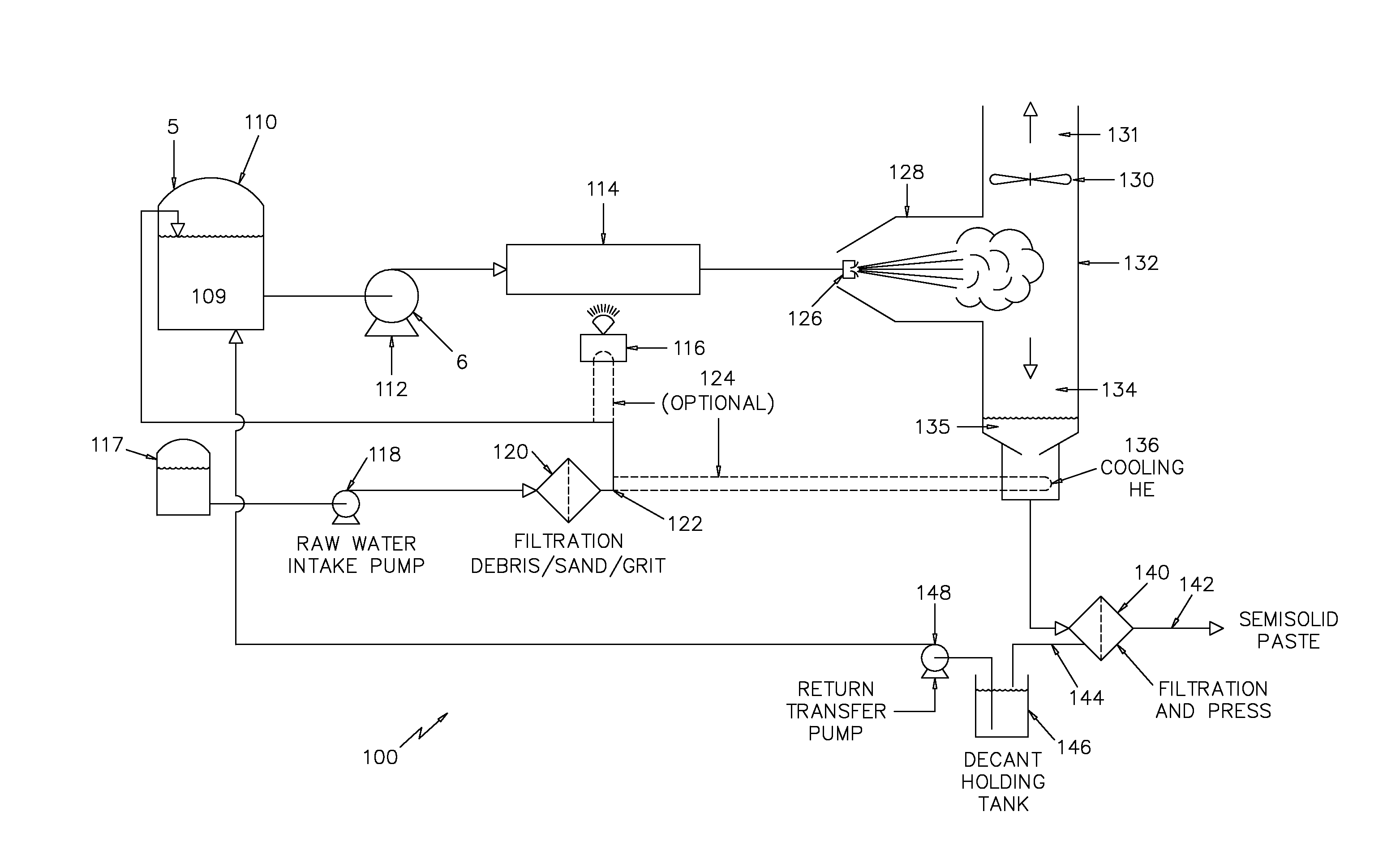
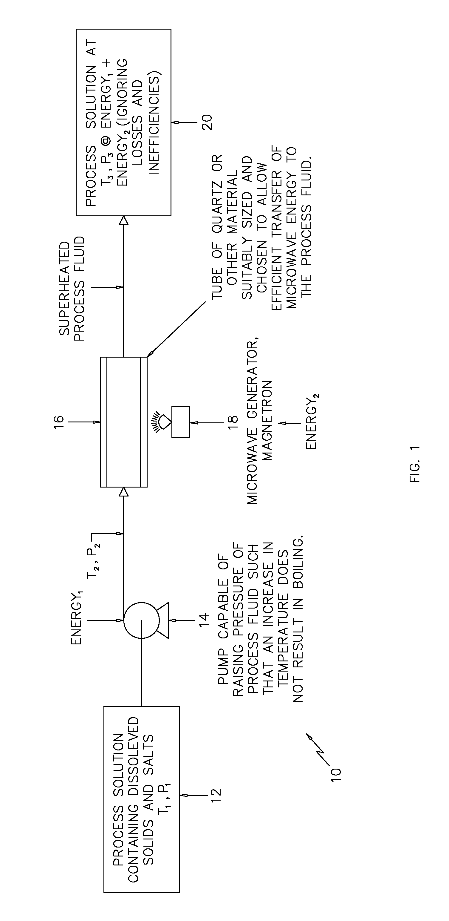
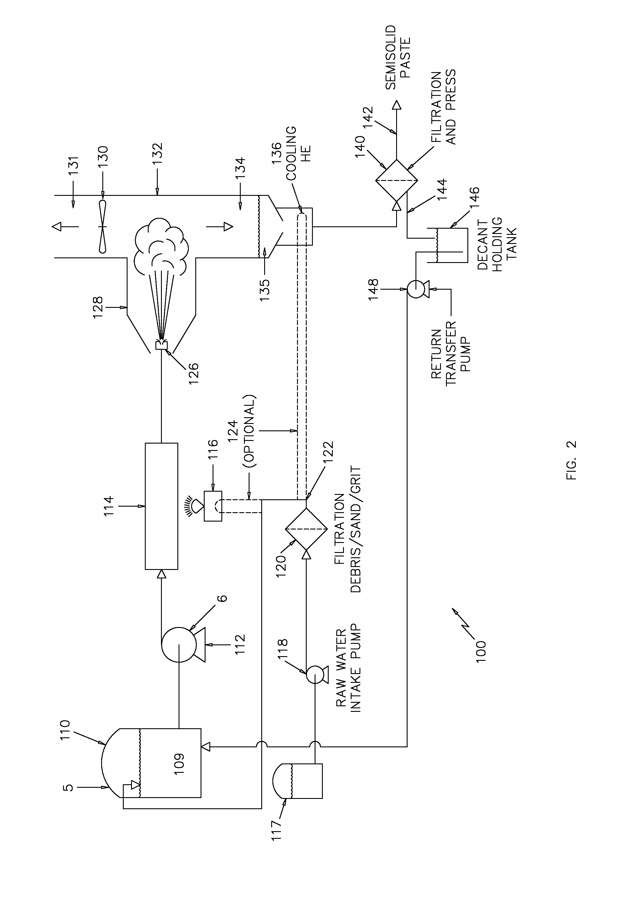
[0018]Referring first to FIG. 1, which depicts a simplified schematic of a process and device 10 for raising the temperature and pressure of a process fluid in accordance with the invention. It is well known that some materials are reflective to microwave energy such as metals and many other materials. In the same way, there are materials such as quartz glass that are very efficient at allowing microwave radiation to pass through.

[0019]A process fluid 12 which may contain contaminants such as dissolved solids and salts is provided to a pump 14 at a given temperature (T1) and pressure (P1). The fluid pump 14, which may be of any well known type, raises the pressure of the process fluid 12 to (P2). Temperatures T1 and T2 are substantially equal. The process fluid is then transferred to a suitably sized and configured quartz tube 16 and a magnetron (electromagnetic energy source) 18 is configured to transmit microwave energy to the process fluid 12 as it flows through the quartz tube 1...


PUM


Abstract

A device and process for removing contaminates from a process fluid employing microwave energy has been described. The use of a quartz tube, which allows for the efficient transfer of microwave energy to a contaminated process fluid is employed to raise the temperature of the process fluid and a flash vaporization technique allows for the removal of uncontaminated fluid. This process decreases the amount of scaling that may collect on the surfaces of the device which increases the devices efficiency and useful life.

Description

BACKGROUND OF THE INVENTION[0001]This invention relates generally to fluid treatment systems, and more particularly to a device and process which employs the use of electromagnetic energy, i.e. microwave energy, to superheat a contaminated fluid and remove contaminants from the fluid.SUMMARY OF THE INVENTION[0002]As a consequence of some natural and industrial process applications, solutions containing high levels of total dissolved solids are generated. One example would be the presence of highly saline solutions known as “produced water” which is a byproduct of hydrocarbon extraction. Disposal of the produced water is a problem where for various environmental reasons reinjection of the fluid is not advisable or even allowed. Because of the high salinity, the solutions are toxic to aquatic creatures and are therefore not suitable for surface disposal. Currently there are two techniques for removal of this fluid. One method concerns the collection and transport in tanker trucks to a...

Claims


Application Information

Patent Timeline
Patent Type & Authority Applications(United States)
IPC IPC(8): B01D3/06H05B6/64
CPCB01D3/06B01D1/0017H05B6/802
Inventor SHUMWAY, SCOTT
Owner SHUMWAY SCOTT
Why Eureka
Try Eureka