Automotive floor structure

a technology for floor structure and automotive, which is applied in the direction of roofs, propulsion by batteries/cells, battery/fuel cell control arrangements, etc. it can solve the problems of increasing the size and/or weight of the vehicle body, reducing the passenger space in the vehicle cabin, and reducing the burden of load transmission on the upper and lower cross members. , to achieve the effect of reducing the burden of load transmission on the upper and lower cross members, reducing the burden of load transmission, and lateral

Active Publication Date: 2013-09-05
HONDA MOTOR CO LTD
View PDF8 Cites 103 Cited by
  • Summary
  • Abstract
  • Description
  • Claims
  • Application Information

AI Technical Summary

Benefits of technology

[0045]In the automotive floor structure according to the present invention, a side impact load input to one floor flame is split into a part conveyed by the first cross member upper and a part conveyed by the first cross member lower, and via these cross members, transmitted from the one floor frame to the other floor frame, and therefore, the burden of load transmission on each of the first cross

Problems solved by technology

Therefore, the side impact load may not be transmitted sufficiently from the floor frame on one side of the vehicle body to the floor frame on the other side and the cross member may be deformed, which may result in unsatisfactory protection of the battery unit from damage.
For this reason, in the conventional structu

Method used


Image

  • Automotive floor structure
  • Automotive floor structure
  • Automotive floor structure

Examples


Embodiment Construction

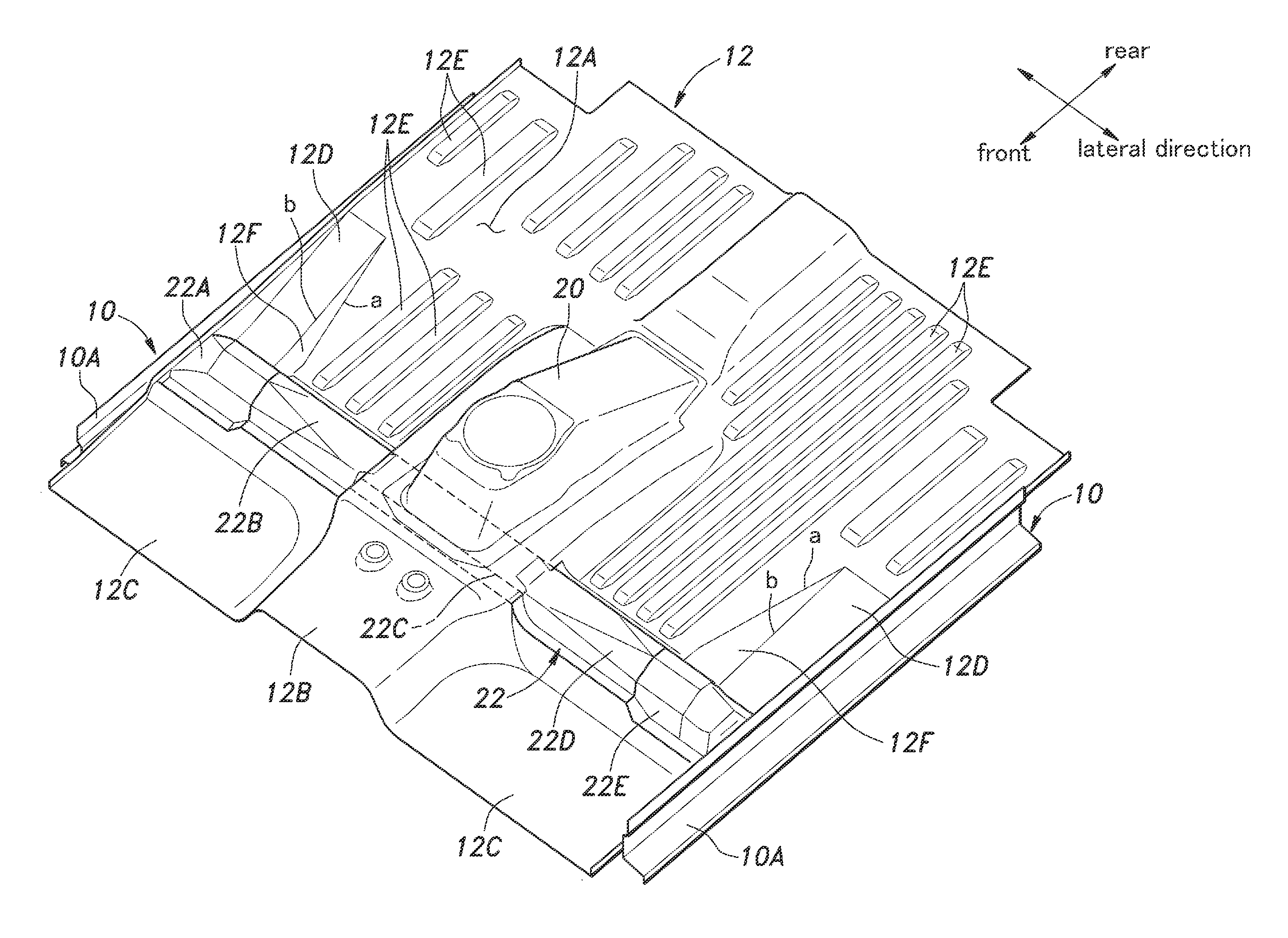
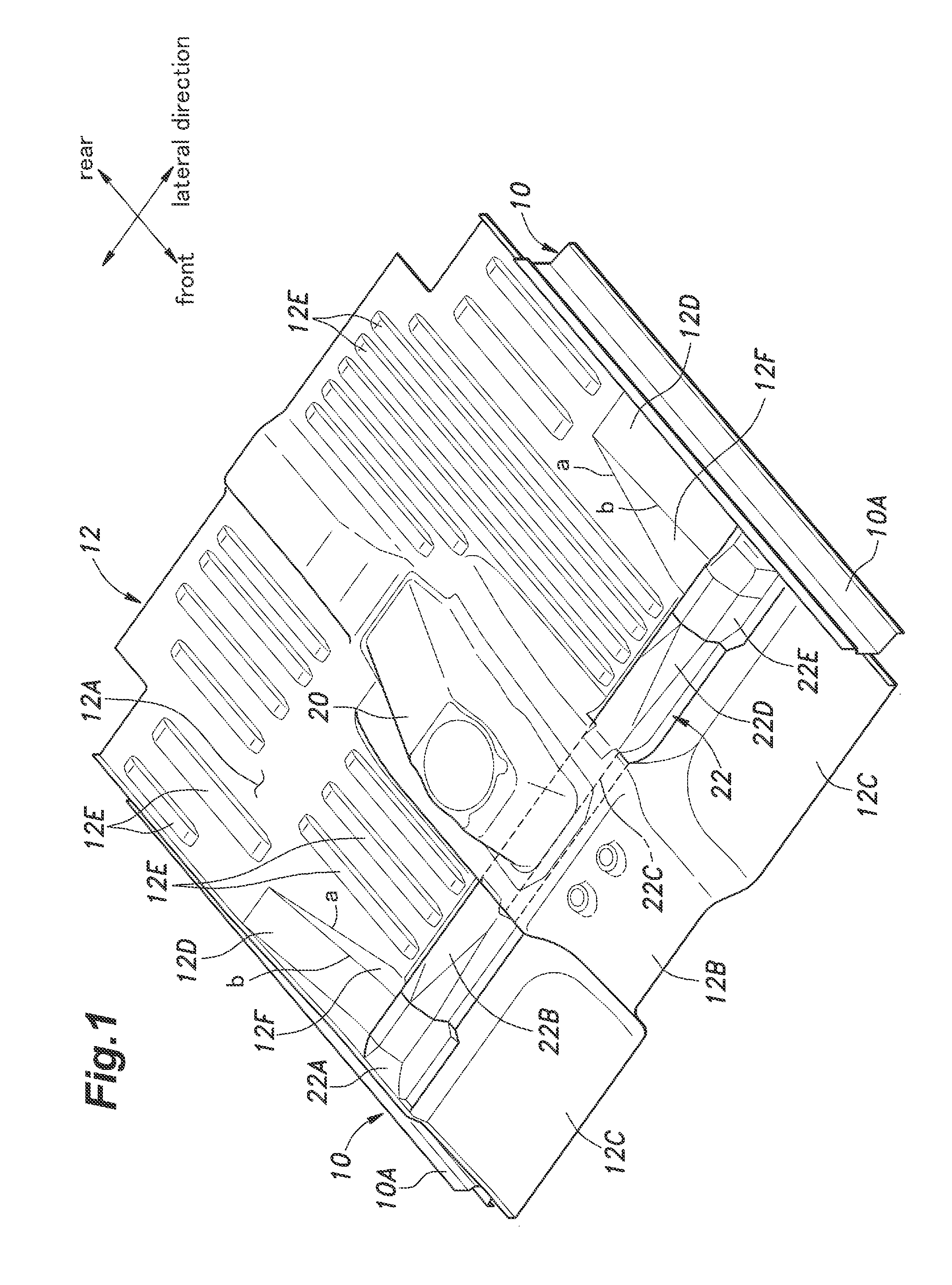
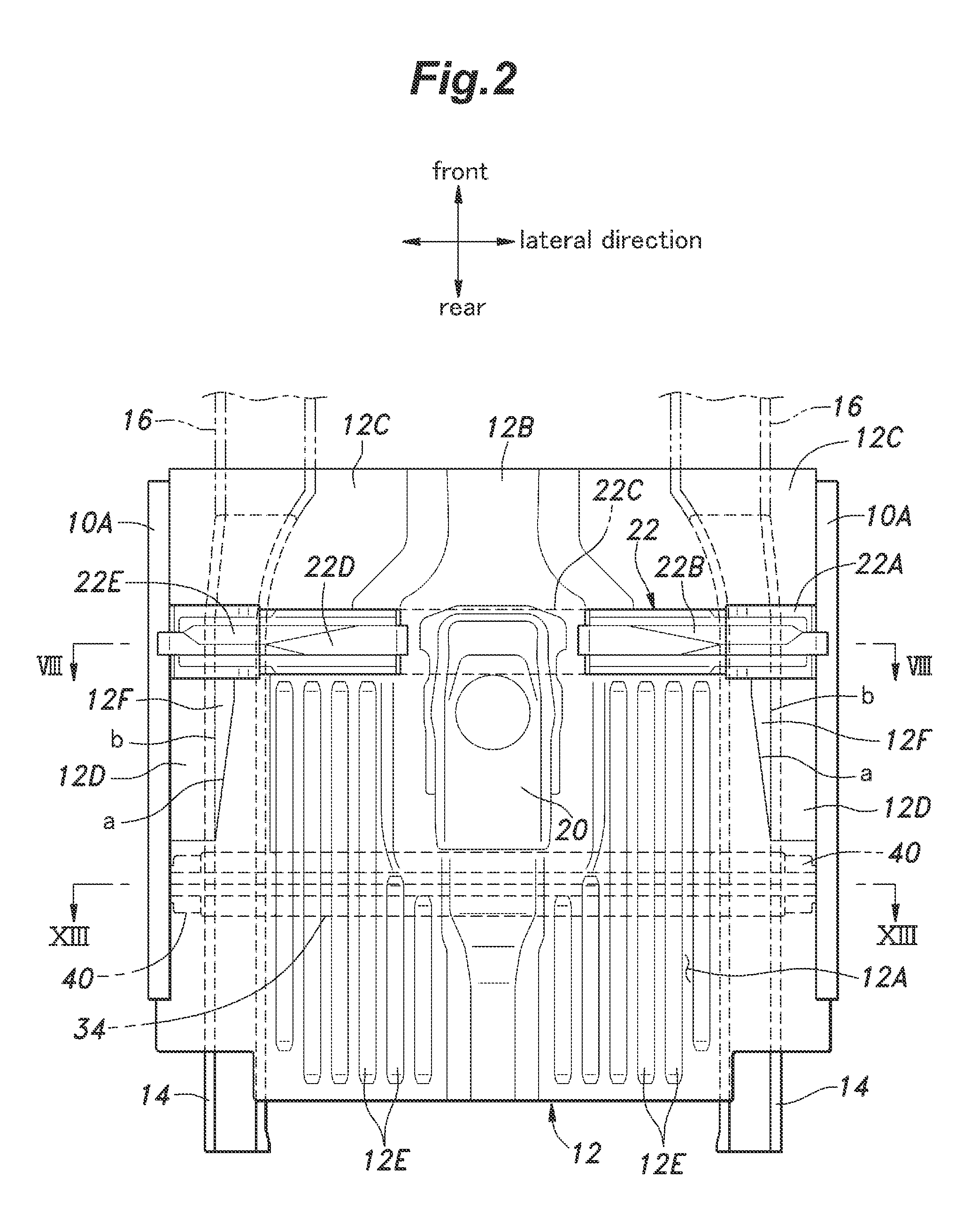
[0061]Now, an embodiment of an automotive floor structure according to the present invention will be described with reference to FIGS. 1 to 15. In the following description, it is assumed that “attachment” is achieved by welding such as spot welding so long as it is not indicated otherwise. Further, a “hat-shaped cross section” refers to a lateral cross section of a member having a groove-shaped cross-sectional portion with a flange piece (welding margin) projecting outward from each side of the groove-shaped cross-sectional portion.

[0062]As shown in FIGS. 1 to 3, the floor structure includes a pair of side sills 10 extending in parallel with each other in a fore-and-aft direction on either side of a vehicle body. Each side sill 10 includes an inner member 10A and an outer member 10B each made of a high tensile steel sheet (high strength steel sheet) and provided with a hat-shaped cross section, where the inner member 10A and the outer member 10B are attached to form a closed cross ...


PUM


Abstract

To achieve efficient and proper transmission of an impact load from a floor frame on one side of a vehicle body to a floor frame on the other side to thereby protect a battery unit from damage, an automotive floor structure includes a first cross member upper and a first cross member lower. the first cross member upper extends in a lateral direction of the vehicle body and has ends attached to left and right side sills, respectively. The first cross member lower extends in the lateral direction below a front floor panel at a position under the first cross member upper, and has ends secured to the left and right floor frames, respectively. The first cross member upper and the first cross member lower vertically sandwich the battery unit therebetween.

Description

TECHNICAL FIELD[0001]The present invention relates to an automotive floor structure, and particularly to a floor structure of an automobile, such as an electronic car, in which a large battery unit is mounted below the floor.BACKGROUND ART[0002]An automobile having a large battery unit mounted therein, such as an electronic car, may have a floor structure including a pair of side sills extending in a fore-and-aft direction on either side of a vehicle body, a front floor panel extending between the side sills, a pair of floor frames (side members) extending in the fore-and-aft direction at positions spaced inward from the two side sills, respectively, in a lateral direction of the vehicle body, and a cross member extending in the lateral direction over the front floor panel (on the cabin side) and having ends attached to the two floor frames, respectively, wherein a battery unit is disposed flatly below the front floor panel between the two floor frames or on the inner side of the tw...

Claims


Application Information

Patent Timeline
IPC IPC(8): B62D25/20
CPCB60K1/04B60K2001/0438B62D25/20B62D25/025B62D25/2036B62D21/157B60L50/64B60L50/66B60L53/80B60L58/21Y02T10/70Y02T10/7072
Inventor YAMAGUCHI, TOSHIYUKIAYUZAWA, SHOTAROKOBAYASHI, SHINYAYAMAMOTO, KOICHI
Owner HONDA MOTOR CO LTD
Why Eureka
Try Eureka