
Optimized designs for embedding webcam modules with superior image quality in electronics displays

a technology of electronics display and embedded cameras, which is applied in the field of embedded cameras, can solve the problems of compromising image quality, webcams integrated into the laptop also need to be very thin, and the laptop is becoming increasingly thin, so as to improve image quality, improve image quality, and expand the configuration

Inactive Publication Date: 2013-09-05
LOGITECH EURO SA
View PDF7 Cites 5 Cited by
  • Summary
  • Abstract
  • Description
  • Claims
  • Application Information

AI Technical Summary

Benefits of technology

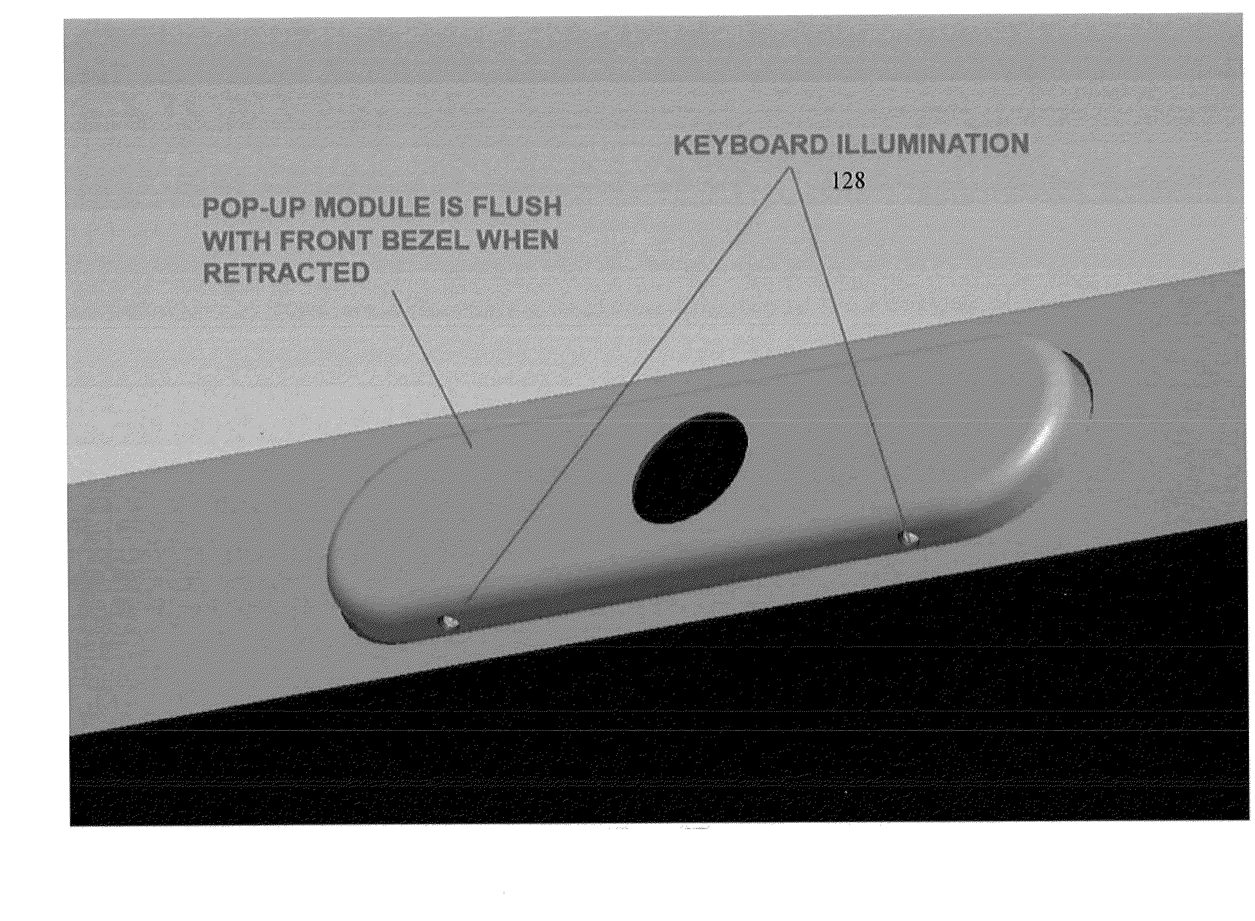
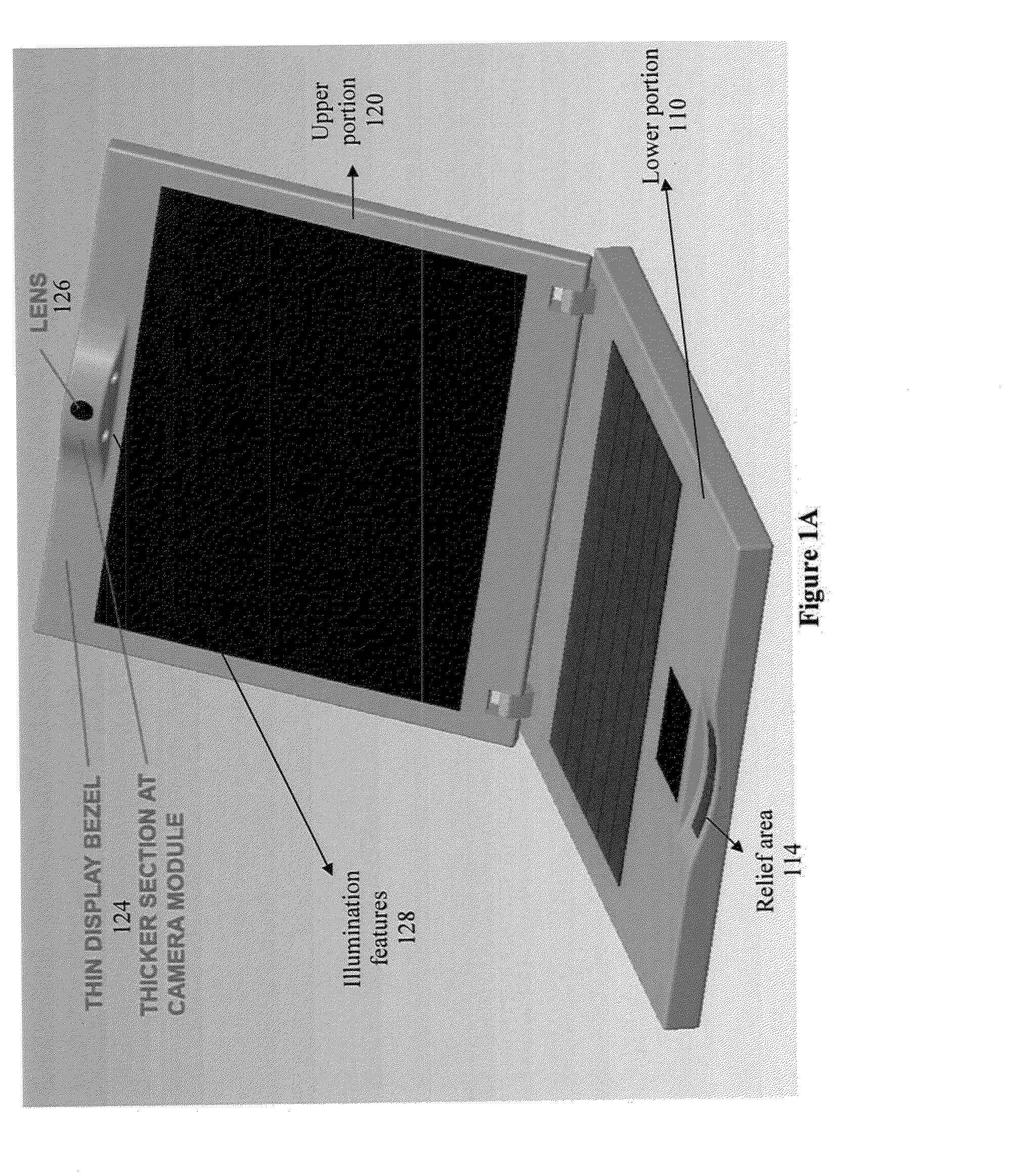
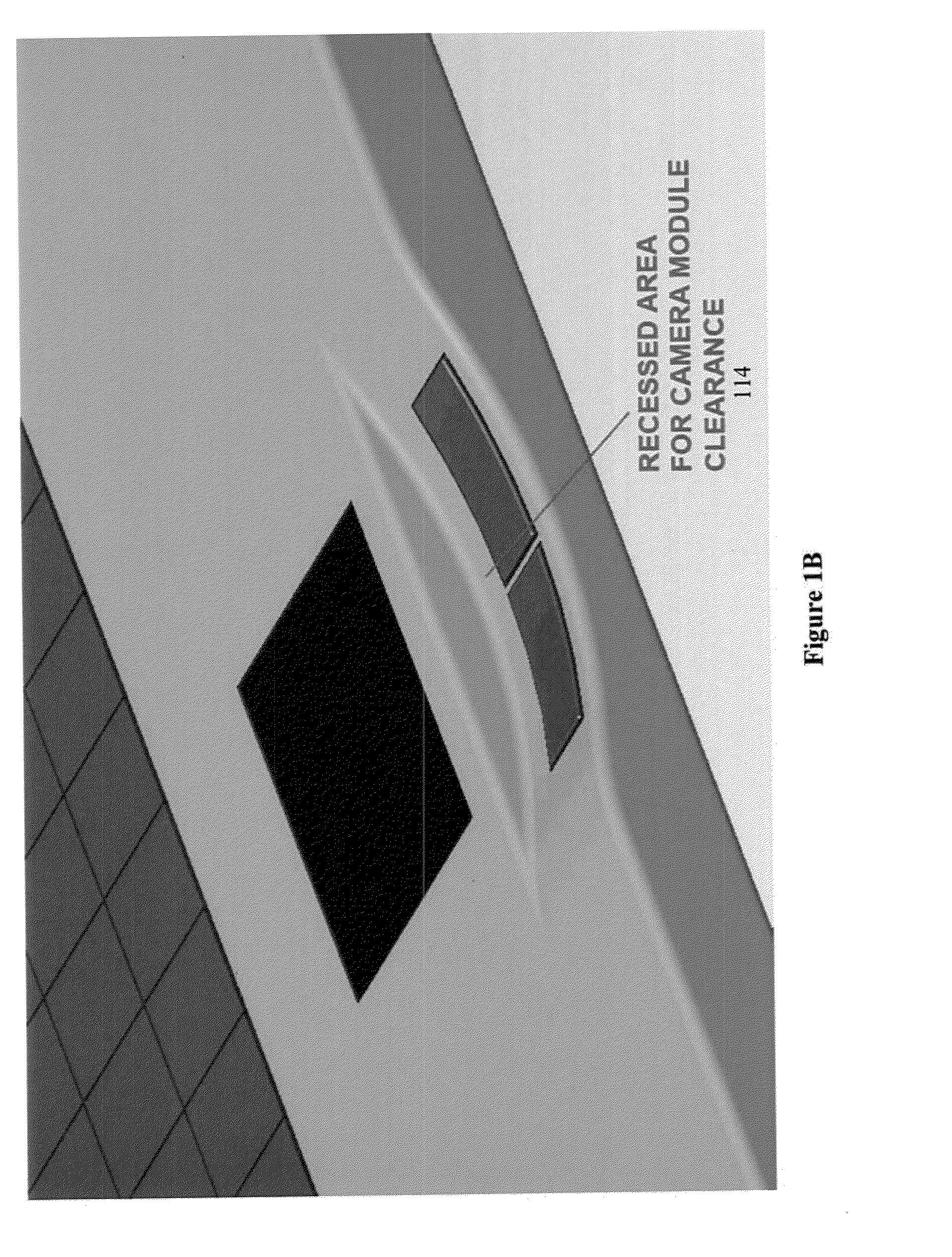
[0011]Various embodiments of the present invention provide for image capturing modules which can be embedded into thin displays (e.g., in laptop computers) and which provide for improved image quality. In accordance with several embodiments, a webcam module embedded in a display has multiple positions. A first position (or a “rest” or “park” position) is the position of the webcam module when it is not in use. In this first position of the webcam module, it is in its most compact configuration, and lends itself to integration into a very thin display. For instance, in one embodiment, this is the position of the webcam module when a laptop into which the webcam module is integrated, is closed. In other positions, the webcam module has a more expanded configuration, thus leading to better image quality. Such an expanded configuration leads, amongst other things, to a larger depth of focus. This can be achieved in some embodiments, for instance, by increasing the distance between a lens and a sensor in the webcam module. In other embodiments, there is no change in the relative position of the lens and the sensor—instead, the webcam module has a closed (or park) position in which the webcam is not used, and at least one open (or view) position. In such embodiments, the closed configuration allows for a more compact configuration of the webcam module integrated into the display, while the open configuration allows for good image quality.
[0014]In still another embodiment, a stepped printed circuit board (PCB) is used. Such a stepped PCB has a thin portion and some thicker portions. The optical module is mounted upon the thin portion so as to accommodate the optical module, while the rest of the substrate is thicker to provide additional stability. Such embodiments allow for a more compact form factor for the webcam module, while still maintaining a high image quality.

Problems solved by technology

However, there are several issues associated with such integration as well.
In particular, laptops are becoming increasingly thinner, and as a result, any webcam integrated into the laptop also needs to be very thin.
However, a webcam that is very thin necessarily has a small depth of focus, thus compromising image quality.
Thus consumers are currently forced to choose between a larger webcam embedded in a device which is thicker and bulkier, and a thinner webcam embedded in an easier to handle device where the thinner webcam provides poorer image quality.
Current webcam modules in displays (e.g., in laptop / notebook computers) have poor image quality.
An indication of the extent to which current notebook webcam module image quality is suffering is offered by the fact that some original equipment manufacturers (OEMs) are retreating back from 1.3 Mega Pixel designs to VGA solutions, because the higher quality solutions are not viable in image capturing modules embedded in the increasingly popular thinner display panels.
In conventional webcam modules, an inherent tradeoff is necessary, because sleek notebook / display designs call for thin display bezels, while high quality webcam optics call for longer optics paths.
As mentioned above, in several cases, current size restrictions for embedded webcam modules cause significant compromise in image quality.

Method used


Image

  • Optimized designs for embedding webcam modules with superior image quality in electronics displays
  • Optimized designs for embedding webcam modules with superior image quality in electronics displays
  • Optimized designs for embedding webcam modules with superior image quality in electronics displays

Examples


Embodiment Construction

[0049]The figures (or drawings) depict a preferred embodiment of the present invention for purposes of illustration only. It is noted that similar or like reference numbers in the figures may indicate similar or like functionality. One of skill in the art will readily recognize from the following discussion that alternative embodiments of the structures and methods disclosed herein may he employed without departing from the principles of the invention(s) herein. It is to be noted that the following discussion relates to video, audio and / or still image data. For convenience, in some places “image” or other similar terms may be used in this application. Where applicable, these are to be construed as including any such data capturable by an image capture device. Further, it is to be noted that the terms “camera” and “webcam” are used various times in this discussion. Where applicable, these term includes various image capture devices such as, but not limited to, digital still cameras, ...


PUM

PropertyMeasurementUnit
thickaaaaaaaaaa
thickaaaaaaaaaa
thicknessaaaaaaaaaa

Abstract

The present invention is an apparatus and method of manufacture for providing image capturing modules which can be embedded into thin displays (e.g., in laptop computers) while providing for improved image quality. In accordance with several embodiments, a webcam module embedded in a display has multiple positions. A first position (or a “rest” or “park” position) is the position of the webcam module when it is not in use. In this first position of the webcam module, it is in its most compact configuration, and lends itself to integration into a very thin display. In other positions, the webcam module has a more expanded configuration, thus leading to better image quality. Such an expanded configuration leads, amongst other things, to a larger depth of focus. In one embodiment, a stepped PCB is used to provide good image quality while maintaining a compact form factor as well as structural rigidity.

Description

CROSS-REFERENCES TO RELATED APPLICATIONS[0001]This application claims the benefit of, and priority to, U.S. provisional application No. 61 / 015,112, entitled “Optimized Designs for Embedding Webcam Modules in Electronic Displays”, filed on Dec. 19, 2007, and is hereby incorporated herein in its entirety,[0002]This application claims the benefit of, and priority to, U.S. Provisional application No. 61 / 046,629, entitled “Use of flex cables for embedding webcam modules in electronics displays”, filed on Apr. 21, 2008, and is hereby incorporated herein in its entirety.[0003]This application is related to co-pending application Ser. No. 11 / 478,898, filed on Jun. 30, 2006, entitled “Computer Monitor with Detachable Module”, which is owned by the assignee of the present invention, and which is hereby incorporated herein in its entirety.BACKGROUND OF THE INVENTION[0004]1. Field of the Invention[0005]This invention relates generally to embedded cameras, and more particularly, to thin webcams ...

Claims


Application Information

Patent Timeline
Patent Type & Authority Applications(United States)
IPC IPC(8): H04N5/225
CPCH04N5/2254Y10T29/49124G03B17/04H04N5/2257H04N23/57
Inventor MARTINEZ, MARKMOAYER, ALILING, KENNETHDEPALLENS, PHILIPPE
Owner LOGITECH EURO SA
Learn More