Component analyzer

a technology of component analyzer and analyzer, which is applied in the field of component analyzer, can solve the problems of inability to downsize the device, inconvenient portability of the device, and large acousto-optic element used for the light source unit, and achieves the effects of easy calculation, easy portability, and easy estimation of the volume of the test obj

Inactive Publication Date: 2013-09-05
SEIKO EPSON CORP
View PDF25 Cites 51 Cited by
  • Summary
  • Abstract
  • Description
  • Claims
  • Application Information

AI Technical Summary

Benefits of technology

[0050]As a method of estimating the volume of the test object, for example, the distance between the test object and the component analyzer may be acquired by focusing processing performed when the taken image is acquired, and the volume of the test object may be obtained by analyzing the taken image. Further, the volume can be estimated by creating a three-dimensional image based on taken images from two points of view. However, it is not preferable to perform complex image processing in the compact component analyzer with high portability in view of power saving. On the other hand, in the configuration described above, for example, using a taken image having the reference material having known dimensions and area or the like and the test object, the dimension ratio of the test object to the reference material or the like may be easily calculated by simple image recognition, and the volume of the test object may be easily estimated.

Problems solved by technology

On the other hand, in the above described device of JP-A-2005-292128, the acousto-optic element used for the light source unit is large and not suitable for portability.
Further, the device performs the component analysis with the test object placed on the turning table within the enclosed space, and there has been a problem that the device is not suitable for size reduction.
Therefore, it is impossible to downsize the device to, for example, a pocket size or the like that can be easily carried.
However, it is necessary to bring the test object into contact with the detection head unit, and, in the case where the test object is a food, for example, there has been a problem that the device is not suitable from a sanitary standpoint and can perform a component analysis of only the contacted part.
In the case where a component analysis with respect to plural points is performed by a device that performs a component analysis on one point of the test object with a detection head brought into contact with the test object, it is necessary to change the contact location of the detection head and measure light intensity in the contact location again, and the analysis becomes complex.
In the configuration described above, the incident angles of the incident light may be limited to the predetermined angle or less by the lens groups, and additionally, the incident angles are further limited by the light incident angle adjustment unit.
According to the configuration, an error is produced compared to the mass measured by the above described mass measurement unit, however, a step of mounting the test object on the mass measurement unit or the like is unnecessary, and the content of the component to be analyzed with respect to the test object may be more readily calculated.
However, it is not preferable to perform complex image processing in the compact component analyzer with high portability in view of power saving.

Method used


Image

  • Component analyzer
  • Component analyzer
  • Component analyzer

Examples


first embodiment

Advantages of First Embodiment

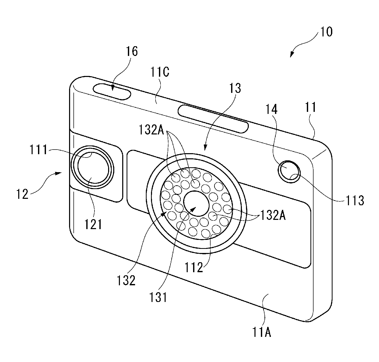
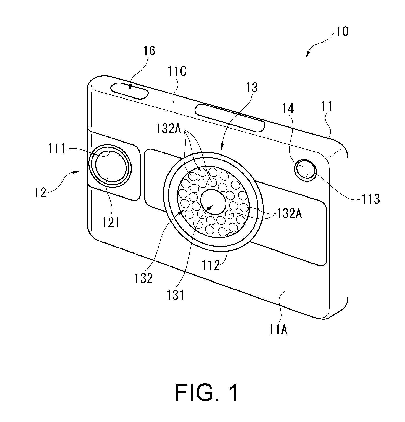
[0196]In the embodiment, the component analyzer 10 includes the casing 11. In the near-infrared imaging window 112 of the casing 11, the light incident part 131 and the light source part 132 are provided, and, within the casing 11, the tunable interference filter 5 that incident light guided by the light incident part 131 enters, the imaging part 133 that receives the light extracted by the tunable interference filter 5 and takes spectroscopic images, and the control unit 17 that performs the component analysis of the test object or the like based on the spectroscopic images are provided.

[0197]In the component analyzer 10, the component analysis of the test object is performed based on the spectroscopic images, and thus, it is not necessary to bring the component analyzer 10 into contact with the test object, and breakage of the test object may be prevented. Further, even when the test object is a food, the component analysis may be contactlessly perfor...

second embodiment

Advantages of Second Embodiment

[0231]In the embodiment, the light incident part 131 includes the viewing angle limiting plate 131A. The viewing angle limiting plate 131A includes the first viewing angle limiting plate 131A1 and the second viewing angle limiting plate 131A2 having the predetermined thickness dimensions along the direction orthogonal to the fixed substrate 51 and the movable substrate 52, i.e., the light traveling direction (Z direction). Further, in the first viewing angle limiting plate 131A1, the plural light transmission parts 131A3 and light blocking parts 131A4 longitudinally extending in the X direction are alternately arranged in the Y direction, and, in the second viewing angle limiting plate 131A2, the light transmission parts 131A3 and the light blocking parts 131A4 longitudinally extending in the Y direction are alternately arranged in the X direction.

[0232]In the configuration, the light at incident angles equal to or more than the predetermined angle may...

third embodiment

[0233]Next, a third embodiment according to the invention will be explained below.

[0234]In the above described first embodiment, the mass estimation unit 197 estimates the specific gravity of the test object based on the water content ratio analyzed by the content ratio analysis unit 196A, and estimates the mass of the test object based on the estimated specific gravity and the estimated volume.

[0235]On the other hand, the third embodiment is different from the first embodiment in that the mass estimation unit 197 does not perform estimation of the specific gravity.

[0236]Note that the third embodiment has the same configuration as that of the first embodiment, and will be explained using the drawings that has been used for the first embodiment.

[0237]In the case where the test object is a food, it is known that its specific gravity takes a nearly constant value. Therefore, in the embodiment, the mass estimation unit 197 estimates the mass of the test object using the preset specific ...


PUM


Abstract

A component analyzer includes a casing, a light source unit, a light incident unit guiding light from a test object into the casing, a tunable interference filter extracting light having a predetermined wavelength from the incident light, an imaging unit receiving the extracted light and taking a spectroscopic image, a control unit performing a component analysis of the test object based on the spectroscopic images, and a display displaying a component analysis result. The light incident unit, the imaging unit, and the control unit are provided within the casing. The tunable interference filter includes a fixed substrate having a fixed reflection film and a movable substrate provided to face the fixed substrate and having a movable reflection film opposed to the fixed reflection film across a gap between reflection films, and an electrostatic actuator changing the gap between reflection films.

Description

BACKGROUND[0001]1. Technical Field[0002]The present invention relates to a component analyzer that takes a spectroscopic image and analyzes a component of a test object from the spectroscopic image.[0003]2. Related Art[0004]Component analyzers that analyze components of objects to be measured are known (for example, see JP-A-2005-292128 and JP-A-2005-127847.[0005]The device disclosed in JP-A-2005-292128 is a calorie measuring device for food. In the device, a food as a test object is mounted on a turning table provided in an enclosed space, light is applied from a light source unit to the food, and the reflected light or transmitted light from the food is received by a light receiving unit. Here, in the light source unit, light applied from a halogen lamp is divided into plural pulsed lights using a light chopper, the divided lights are spectroscopically separated in resolution of 2 nm using an acousto-optic element, and the spectroscopically-separated lights are applied to the food...

Claims


Application Information

Patent Timeline
Patent Type & Authority Applications(United States)
IPC IPC(8): G01J3/45
CPCG01J3/45G01J3/0291G01J1/06G01J3/0264G01J3/0289G01J3/027G01J3/28G01J5/10G01J2005/0077G01J3/0229G01J3/26
Inventor SAKURAI, KAZUNORI
Owner SEIKO EPSON CORP
Why Eureka
Try Eureka