Multi-Mode Operation and Control of a Resonant Converter

a resonant converter and multi-mode technology, applied in the field of electronic power conversion and methods, can solve problems such as modern controllers entering a burst mod

Active Publication Date: 2013-09-05
INFINEON TECH AG
View PDF25 Cites 119 Cited by
  • Summary
  • Abstract
  • Description
  • Claims
  • Application Information

AI Technical Summary

Problems solved by technology

Under low-load conditions, which occur when a power consumption of the load is very low, some modern controllers enter a burst mode.

Method used


Image

  • Multi-Mode Operation and Control of a Resonant Converter
  • Multi-Mode Operation and Control of a Resonant Converter
  • Multi-Mode Operation and Control of a Resonant Converter

Examples


Embodiment Construction

[0013]The making and using of the presently preferred embodiments are discussed in detail below. It should be appreciated, however, that the present invention provides many applicable inventive concepts that can be embodied in a wide variety of specific contexts. The specific embodiments discussed are merely illustrative of specific ways to make and use the invention, and do not limit the scope of the invention.

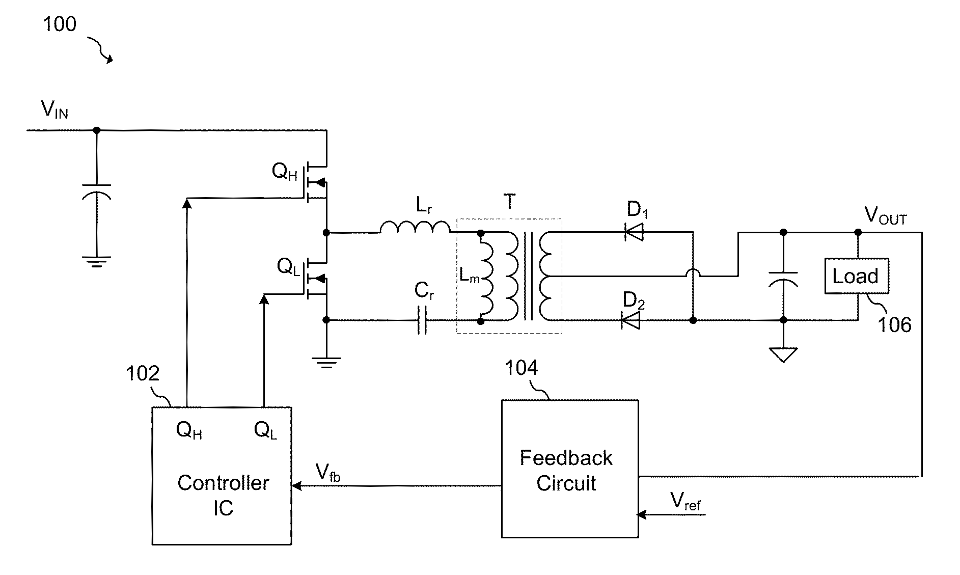
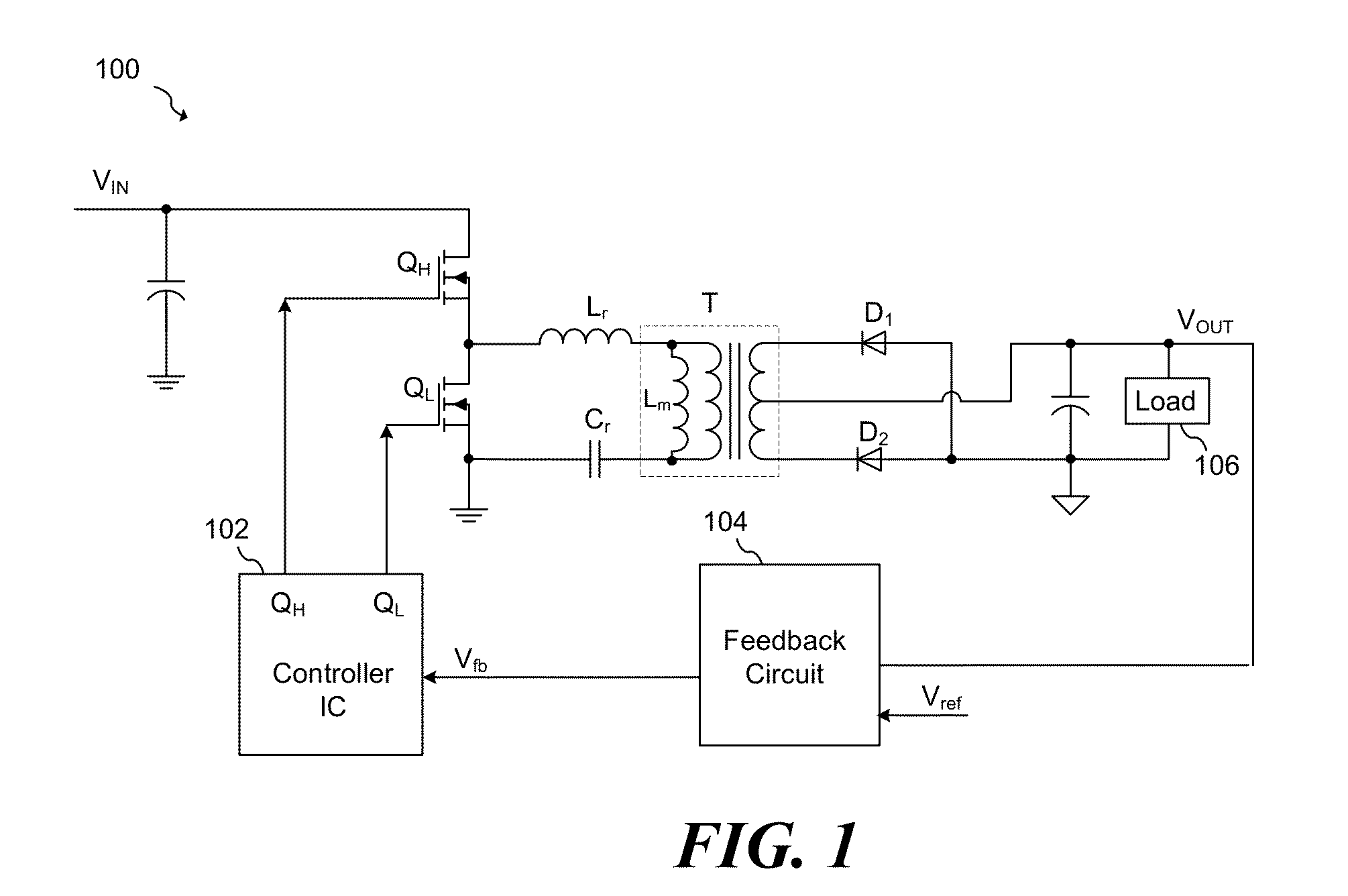
[0014]The present invention will be described with respect to exemplary embodiments in a specific context, namely a resonant switched-mode power converter formed with a controller that is configured to operate in a power saving switching mode during low load conditions. Embodiments of the present invention may also be applied to other types of electronic power conversion devices and other power conversion architectures.

[0015]A switched-mode power converter (also referred to as a “power converter” or “regulator”) is a power supply or power processing circuit that converts an i...


PUM


Abstract

In accordance with an embodiment, a method of controlling a switched-mode power includes generating a feedback signal proportional to an output of the switched-mode power supply, and operating the switched-mode power supply in a normal mode. If the feedback signal crosses a first threshold, the switched-mode power operates in a second operating mode. In the first operating mode the pulse modulated signal is adjusted to regulate a feedback signal to a first signal level, and in the second operating mode, a dead-time of the pulse modulated signal is adjusted to signal to regulate a feedback signal to a second signal level different from the first signal level. The method further includes driving a switch of the switched-mode power supply with the pulse modulated signal.

Description

TECHNICAL FIELD[0001]An embodiment of the invention relates generally to electronic power conversion and methods, and more particularly to the use of a controller for a power switch in a switched-mode power converter.BACKGROUND[0002]Switching converters are widely used in the field of power conversion. A switching converter includes at least one switch that is configured to generate a pulse-width modulated (PWM) voltage from an input voltage, and a rectifier arrangement that receives the PWM voltage and generates an output voltage to be supplied to a load. Usually the rectifier arrangement includes at least one inductive storage element, such as a choke, and at least one capacitive storage element, such as a capacitor. The PWM voltage is generated by switching the switching element on and off in accordance with a PWM drive signal. The drive signal is provided by a controller dependent on the output voltage. The controller is configured to vary the duty cycle of the drive signal in o...

Claims


Application Information

Patent Timeline
Patent Type & Authority Applications(United States)
IPC IPC(8): H02M3/335
CPCH02M3/3376Y02B70/16Y02B70/1433H02M2001/0035Y02B70/10H02M1/0035H02M3/33571H02M3/01H02M3/33507H02M3/33546H02M1/0025
Inventor ZHANG, GUOXINGMAO, MINGPING
Owner INFINEON TECH AG
Why Eureka
Try Eureka