Fiber laser cavity optical engine package and method of making the same

a technology of optical engine and fiber laser cavity, which is applied in the field of fiber management, can solve the problems of difficult placement of fibers within the ring-shape body, affecting the reliability of the fiber laser cavity stored in the package, so as to improve the fiber and thermal management capability

Active Publication Date: 2013-09-05
OFS FITEL LLC
View PDF5 Cites 8 Cited by
  • Summary
  • Abstract
  • Description
  • Claims
  • Application Information

AI Technical Summary

Benefits of technology

[0004]Therefore, an objective of the present invention is to provide fiber laser cavity packages having improved fiber and thermal management capabilities and methods of making such fiber laser cavity packages. According to one embodiment of the present invention, a multi-layer fiber laser cavity package is provided. The multi-layer fiber laser cavity package includes a first layer containing one or more elements of a fiber laser cavity, and one or more layers stacked on top of the first layer and containing the rest of the elements of the fiber laser cavity. The elements are different portions of the fiber laser cavity and include a gain fiber, a grating, a splice and a tapered fiber bundle (TFB). Substantially all of the fiber laser cavity in the package is in contact with a heat-conducting. And, the fiber laser cavity passes from one layer to another layer without any fiber crossings.
[0005]According to another embodiment of the present invention, a method of making a multi-layer fiber laser cavity package is provided. The method includes the steps of grouping elements of a fiber laser cavity into two or more sections, and stacking one section on top of ano...

Problems solved by technology

However, the demand for high-power application generates unwanted heat, which undermines reliability of the fiber laser cavity stored in the package.
Although the ring-shape body has means to increase heat transfer to enhance...

Method used


Image

  • Fiber laser cavity optical engine package and method of making the same
  • Fiber laser cavity optical engine package and method of making the same
  • Fiber laser cavity optical engine package and method of making the same

Examples


Embodiment Construction

[0018]In the following description, similar components are referred to by the same reference numeral to enhance the understanding of the invention through the description of the drawings. Also, unless otherwise explicitly specified herein, the drawings are not drawn to scale.

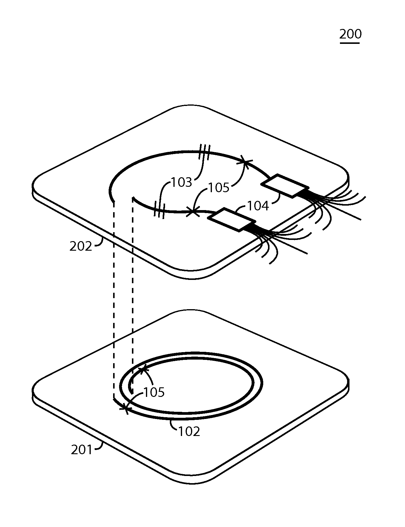
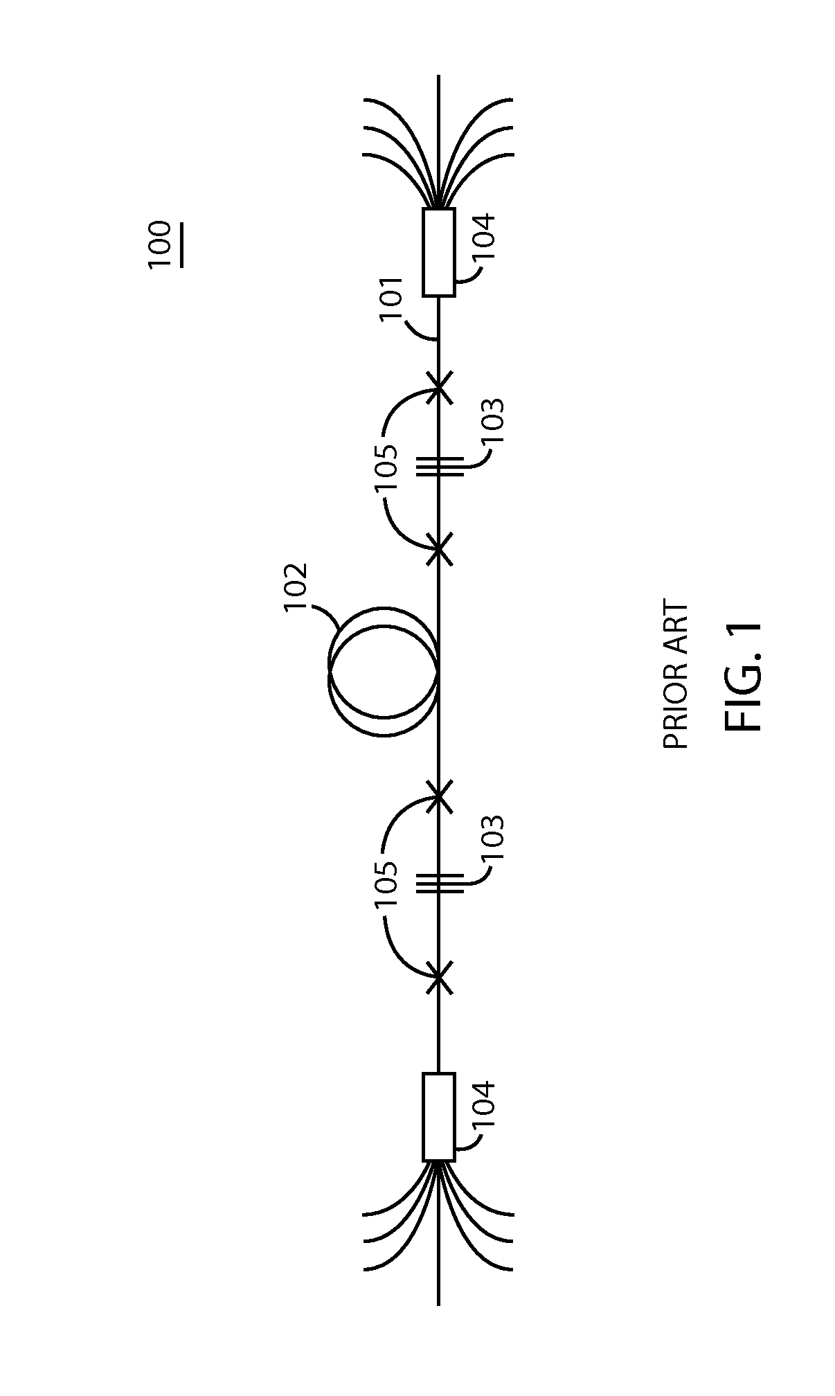
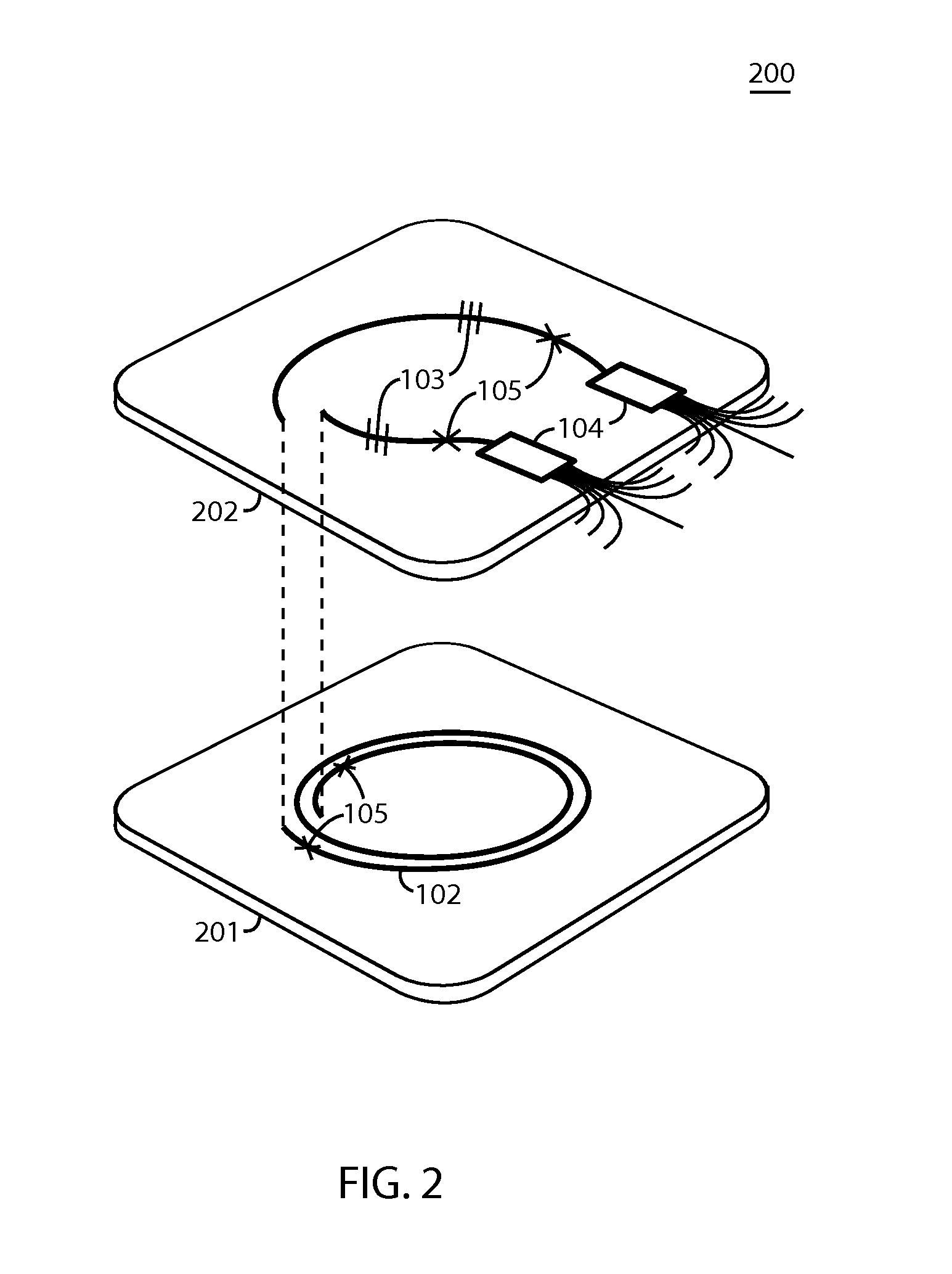
[0019]Typical configuration of a conventional fiber laser cavity 100 is shown in FIG. 1. A fiber laser cavity 100 to be stored in a package typically includes a gain fiber 102, one or more gratings 103, one or more tapered fiber bundles (TFB) 104, and one or more splices 105. Those elements are optically connected together to form the fiber laser cavity 100.

[0020]High-power fiber laser cavity packages must be designed to dissipate unwanted heat accumulated by different elements of a fiber laser cavity and provide mechanical robustness and protection for the cavity. One way to address the issue is better fiber management within a package. Poor fiber management within the fiber laser package creates one or more fi...


PUM

PropertyMeasurementUnit
Thermal conductivityaaaaaaaaaa
Electrical conductoraaaaaaaaaa
Heataaaaaaaaaa

Abstract

Embodiments of the invention include a fiber laser cavity package having improved fiber management and thermal management capability and methods of making such fiber laser cavity package. Each element of the fiber laser cavity is grouped into plurality of sections and each section is placed onto a heat conducting surface within the fiber laser cavity package to dissipate unwanted heat from the elements. When the fiber laser cavity is stored in the package, the fiber laser cavity is arranged such that fiber crossings are substantially reduced or eliminated within the package.

Description

CROSS-REFERENCE TO A RELATED APPLICATION[0001]The present application claims the priority benefit of U.S. Provisional Patent Application Ser. No. 61 / 606,988, entitled “Fiber laser optical engine package,” filed on Mar. 5, 2012, which is owned by the assignee of the present application, and which is incorporated herein by reference in its entirety.TECHNICAL FIELD[0002]This invention generally relates to fiber management, and more particularly, to fiber management of a high-power fiber laser cavity within a package.BACKGROUND OF THE INVENTION[0003]Essential components of a fiber laser are a fiber laser cavity and pump diodes. The fiber laser cavity is a fiber-based, resonant optical cavity with an optical gain section, and is usually stored in a package to enhance reliability. However, the demand for high-power application generates unwanted heat, which undermines reliability of the fiber laser cavity stored in the package. In order to address the issue, U.S. Pat. No. 7,400,812 disclo...

Claims


Application Information

Patent Timeline
IPC IPC(8): H01S3/04B29D11/00
CPCH01S3/0675H01S3/06704B29D11/00H01S3/0405Y10T29/49826H01S3/042H01S3/04
Inventor DONG, HAOHOLLAND, WILLIAM R.PORQUE, JEROME C.STRACHAN, WILLIAM J.
Owner OFS FITEL LLC
Why Eureka
Try Eureka