Sound generating device for vehicle, and sound generating method for vehicle

a sound generation device and vehicle technology, applied in the direction of machines/engines, combustion air/fuel air treatment, instruments, etc., can solve the problems of difficult detection of the sound pressure of the air intake, weak air intake sound, irritating sound generated from the loudspeaker, etc., to achieve less noise, enhance driving experience, and comfort sound

Active Publication Date: 2013-09-05
YAMAHA CORP
View PDF2 Cites 24 Cited by
  • Summary
  • Abstract
  • Description
  • Claims
  • Application Information

AI Technical Summary

Benefits of technology

[0038]With the sound generating method for a vehicle according to the present invention, it is possible to generate, inside a vehicle, a comfortable sound which is less noisy and close to the actual air intake sound of the engine.
[0039]Note that, in the present invention, it is preferred that the loudspeaker is arranged so as to generate the air intake sound in the vehicle from a side on which the engine is arranged in a direction toward the inside of the vehicle cabin. It is further preferred that the loudspeaker is arranged toward the driver seat. With this configuration, the air intake sound reproduced from the loudspeaker is audible from the side on which the engine is arranged, and hence the occupant may feel as if he/she heard the actual air intake sound of the engine. In addition, the air intake sound is reproduced from the loudspeaker toward the driver sitting on the driver seat, and hence the air intake sound is audible directly to the driver so that the driving feel is enhanced.
[0040]Further, an odd or even number of loudspeakers may be provided, bu

Problems solved by technology

Therefore, when the sound pressure sensors are installed on the air cleaner and the outside air inlet of the air cleaner, the air intake sound becomes weaker and thus the sound pressure of the air intake sound is not easily detected.
When the sound pressure sensors are installed on the air intake manifold, the sound pressure sensors are located close to the engine that generates combustion sound, and hence the fluctuation in pulsation becomes larger, which leads to a problem in that the sound generated from the loudspeaker becomes harsh, irritating sou

Method used


Image

  • Sound generating device for vehicle, and sound generating method for vehicle
  • Sound generating device for vehicle, and sound generating method for vehicle
  • Sound generating device for vehicle, and sound generating method for vehicle

Examples


first embodiment

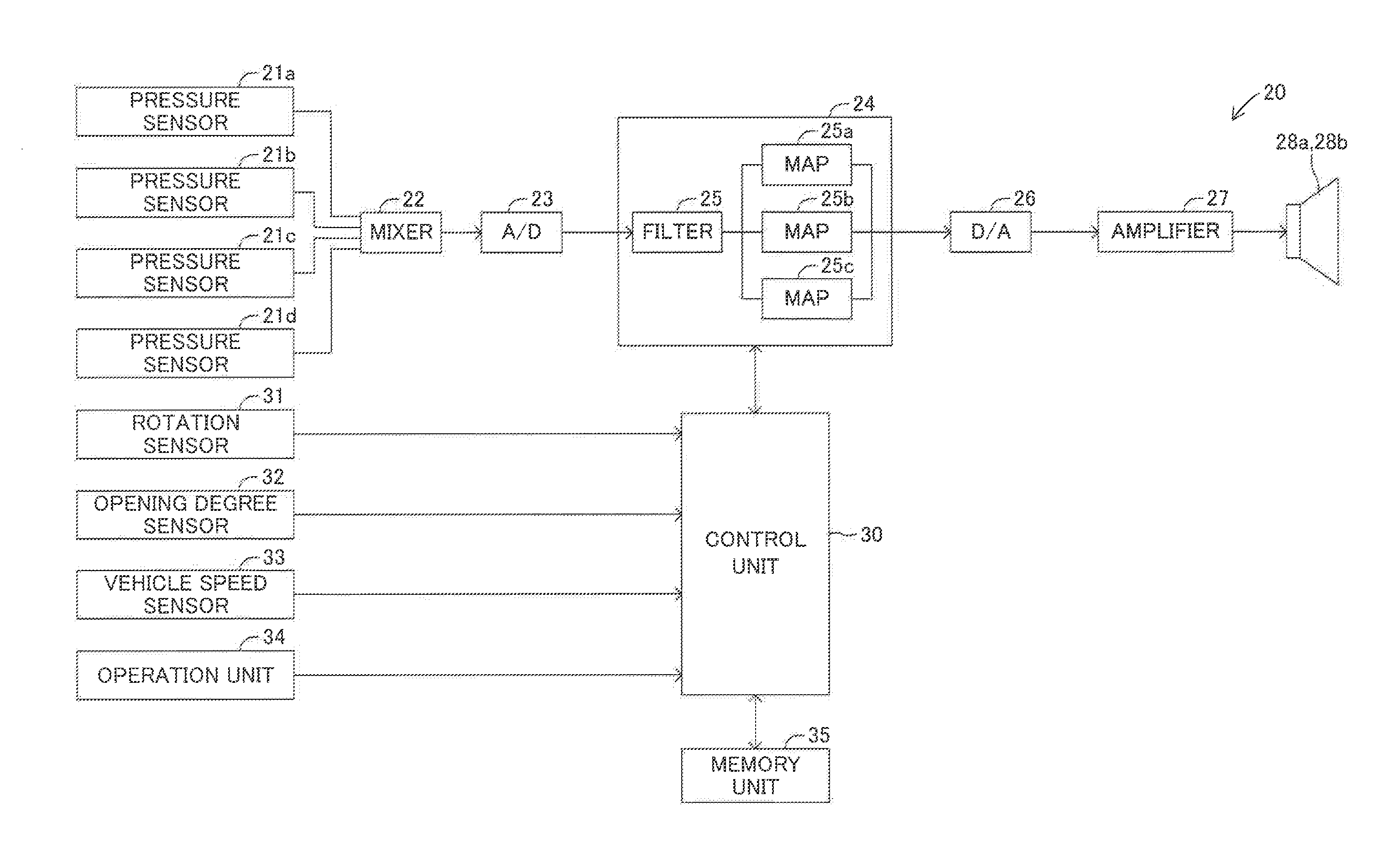
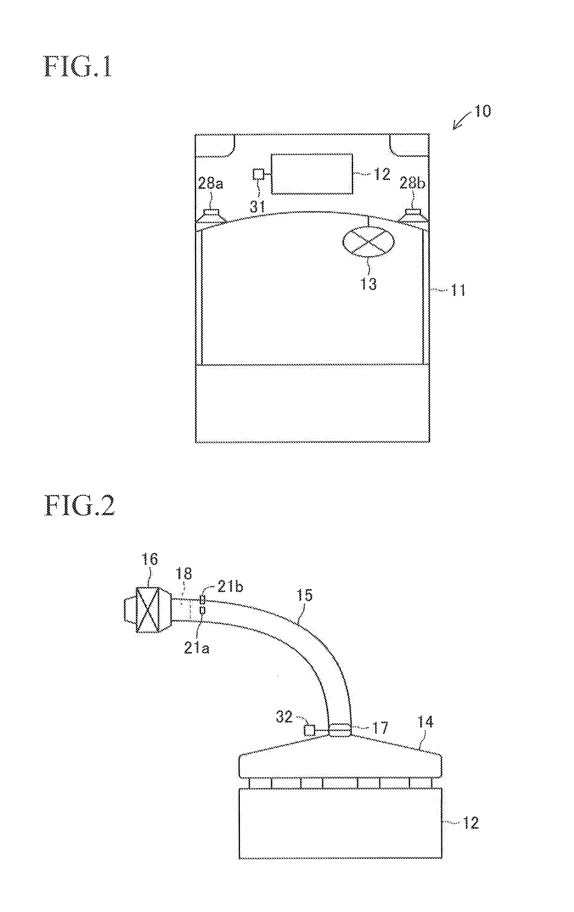
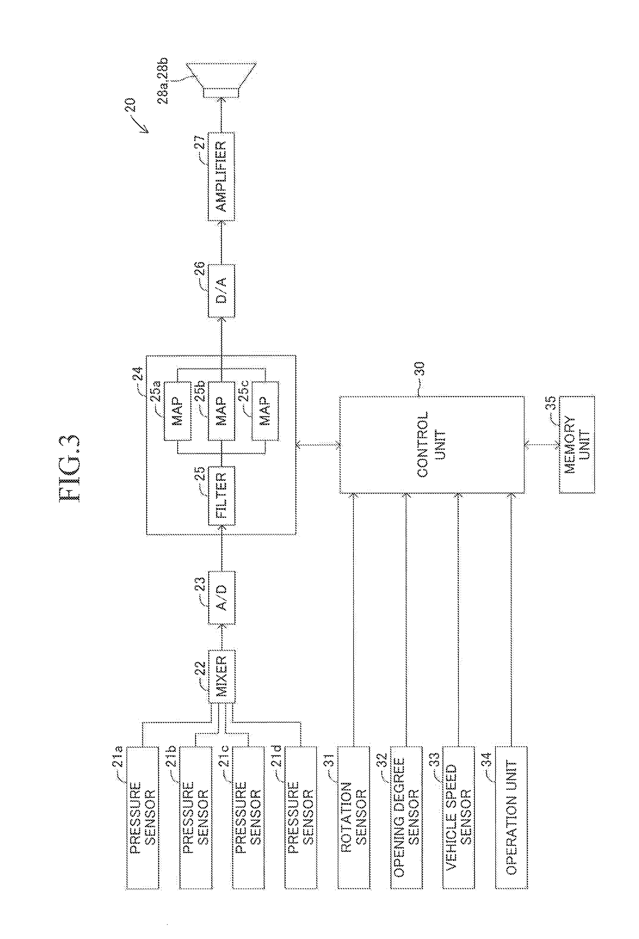
[0058]In the following, a first embodiment of the present invention is described with reference to the drawings. FIG. 1 schematically illustrates an automobile 10 including a sound generating device 20 for a vehicle (see FIG. 3) according to this embodiment. The automobile 10 is a front-engine, front-wheel-drive (FF) car or a front-engine, rear-wheel-drive (FR) car, which includes an engine 12 arranged at the front center of a vehicle body 11. The automobile 10 includes a pair of front wheels (not shown) provided on both sides in the front of the vehicle body 11, a pair of rear wheels (not shown) provided on both sides in the rear of the vehicle body 11, and a steering wheel 13. As illustrated in FIG. 2, an air cleaner 16 is connected to the engine 12 via a surge tank 14 and an air intake duct 15. A throttle body 17 is installed at a position where the surge tank 14 and the air intake duct 15 are coupled to each other. An air flow meter 18 is installed at an end portion of the air i...

second embodiment

[0084]FIG. 12 illustrates a configuration of a sound generating device 40 for a vehicle according to a second embodiment of the present invention. The sound generating device 40 for a vehicle includes a noise gate processing unit 42 and a noise reduction processing unit 43. Other components of the sound generating device 40 for a vehicle are the same as those of the above-mentioned sound generating device 20 for a vehicle. Thus, in FIG. 12, the same components are represented by the same reference symbols. The noise gate processing unit 42 performs noise gate processing for the electric signal synthesized by the mixer 22. The noise gate processing is performed for the purpose of reducing noise. Specifically, when the value of the input signal is equal to or less than a predetermined threshold value, the gain of a frequency spectrum is decreased to close a gate, and when the value of the input signal is equal to or more than the predetermined threshold value, the gate is opened to se...

third embodiment

[0087]FIG. 13 illustrates a configuration of a sound generating device 50 for a vehicle according to a third embodiment of the present invention. The sound generating device 50 for a vehicle includes an acceleration sensor 51 instead of the rotation sensor 31, the opening degree sensor 32, and the vehicle speed sensor 33 of the above-mentioned sound generating device 40 for a vehicle. The acceleration sensor 51 may be installed at, for example, a center bottom portion of the vehicle body 11 of the automobile 10 illustrated in FIG. 1. Other components of the sound generating device 50 for a vehicle are the same as those of the above-mentioned sound generating device 40 for a vehicle. Thus, the same components are represented by the same reference symbols, and description thereof is therefore omitted herein.

[0088]As described above, the sound generating device 50 for a vehicle includes the acceleration sensor 51. Accordingly, based on a value of acceleration detected by the accelerati...


PUM


Abstract

Provided is a sound generating device (20) for a vehicle, including: a plurality of pressure sensors (21a to 21d) for detecting air pressures of an air intake sound of an engine (12) and outputting the air pressures as sound pressure signals; a signal processing unit (24) for performing processing of changing the sound pressure signals in accordance with a driving condition of a vehicle (10); and loudspeakers (28a and 28b) for outputting the sound pressure signals as the air intake sound of the engine (12). Then, the plurality of pressure sensors (21a to 21d) are provided at an interval in a circumferential direction of an outer periphery of an air intake duct (15) at positions in a vicinity of an air flow meter (18) on an air cleaner (16) side with respect to a center of the air intake duct (15), the air intake duct (15) connecting the air cleaner (16) to a throttle body (17).

Description

TECHNICAL FIELD[0001]The present invention relates to a sound generating device for a vehicle and a sound generating method for a vehicle, which are configured to transmit an air intake sound of an engine of a vehicle to an occupant inside the vehicle.BACKGROUND ART[0002]In vehicles such as an automobile provided in recent years, in order to enhance the comfort level of occupants and prevent emission of noise to the outside of the vehicle, engine sound and other sound generated in association with a running condition of the vehicle have been reduced to the extent possible. With this configuration, however, there arises a problem in that the actual running condition such as vehicle speed and the sound audible to the occupant are less related to each other and, as a result, the driving feel of the automobile is deteriorated. Therefore, there has been developed a sound generating device for a vehicle, which is configured to generate the engine sound from a loudspeaker only toward the i...

Claims


Application Information

Patent Timeline
IPC IPC(8): B60Q5/00
CPCB60Q5/00B60R11/0217F02M35/021G10K15/02F02M35/1294G10K11/22F01N1/065F02M35/1038
Inventor OSAWA, HIDEKIMARUYAMA, HEIJISUZUKI, YASUYUKIKUNO, YOSUKEONITSUKA, HIROFUMIHONJI, YOSHIKAZU
Owner YAMAHA CORP
Why Eureka
Try Eureka