Automated track surveying and ditching

a technology of automatic surveying and ditching, applied in the field of railroad track maintenance, can solve the problems of laborious conventional ditch construction and maintenance, unsatisfactory effects,

Active Publication Date: 2013-09-05
HERZOG RAILROAD SERVICES
View PDF7 Cites 31 Cited by
  • Summary
  • Abstract
  • Description
  • Claims
  • Application Information

AI Technical Summary

Benefits of technology

[0012]The soil units are then analyzed, by a computer, by an analyst, or both to determine if the soil units appear to be appropriate and to detect any anomalies in the soil units. If such anomalous soil units are detected, images corresponding to the track location are reviewed to determine the possible reason for the anomalous soil units. If necessary, the anomalous soil units can be adjusted to more appropriate amounts. Once the anomalous soil units are adjusted, the ditch overlays for the locations having anomalous soils are also adjusted. The set of ditch overlays can then be entered into a computer system on an excavator which is provided with position coordinate systems. When the excavator is positioned along the section of railway for maintenance of the ditch, the ditch overlay associated with the current location can be retrieved and viewed by the operator for guidance in excavating or replacing soil in the ditch to achieve the desired profile at that location.
[0013]The survey vehicle may, for example, be a road vehicle such as a pick-up truck equipped with retractable flanged wheels for traveling on rails, such as a Hy-Rail equipped vehicle (trademark of Harsco Technologies LLC).

Problems solved by technology

If the ditch is not constructed properly, water can pool up or drain away to an unforeseen location, possibly causing undesired effects such as erosion or the li

Method used


Image

  • Automated track surveying and ditching
  • Automated track surveying and ditching
  • Automated track surveying and ditching

Examples


Embodiment Construction

[0035]As required, detailed embodiments of the present invention are disclosed herein; however, it is to be understood that the disclosed embodiments are merely exemplary of the invention, which may be embodied in various forms. Therefore, specific structural and functional details disclosed herein are not to be interpreted as limiting, but merely as a basis for the claims and as a representative basis for teaching one skilled in the art to variously employ the present invention in virtually any appropriately detailed structure.

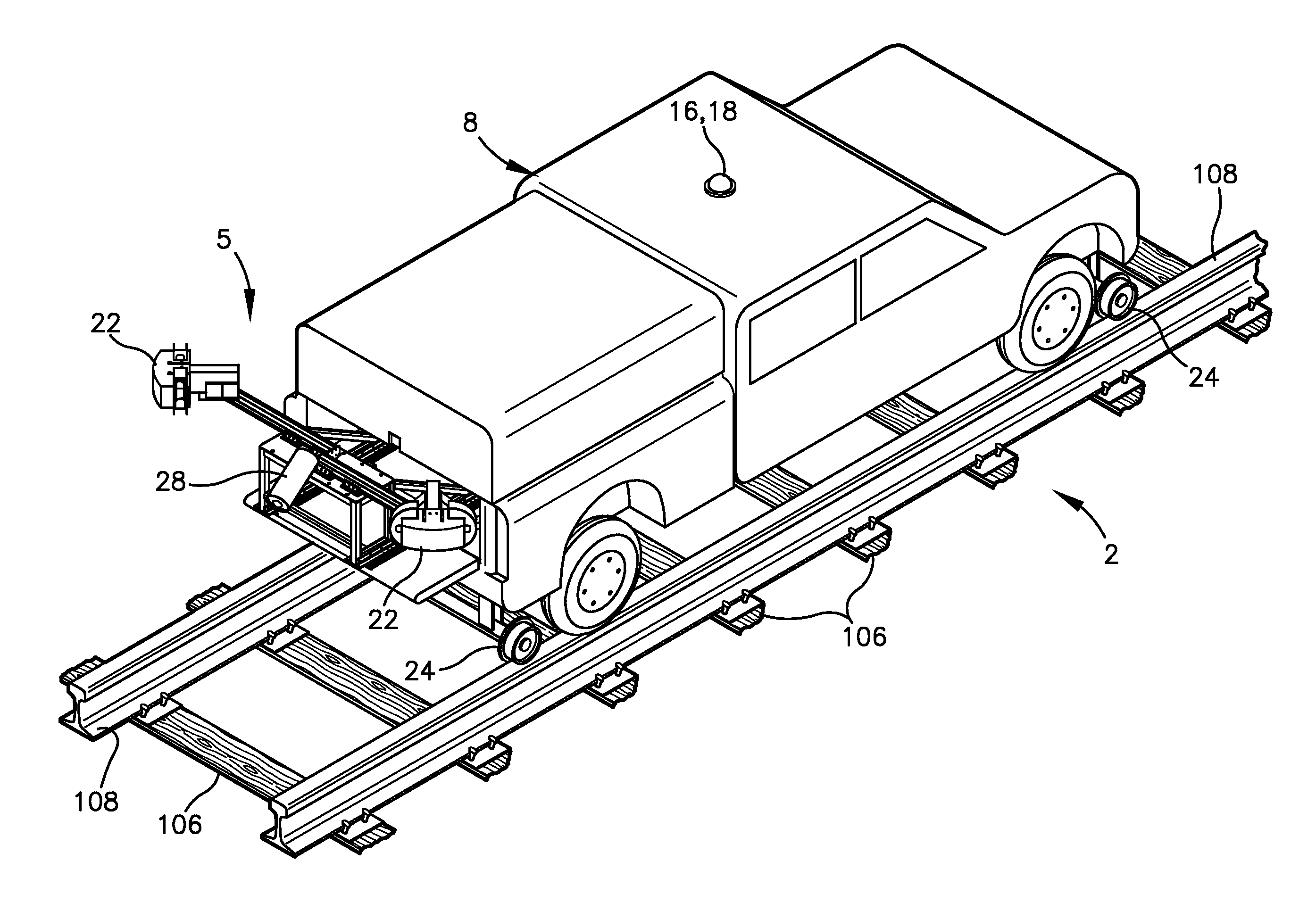
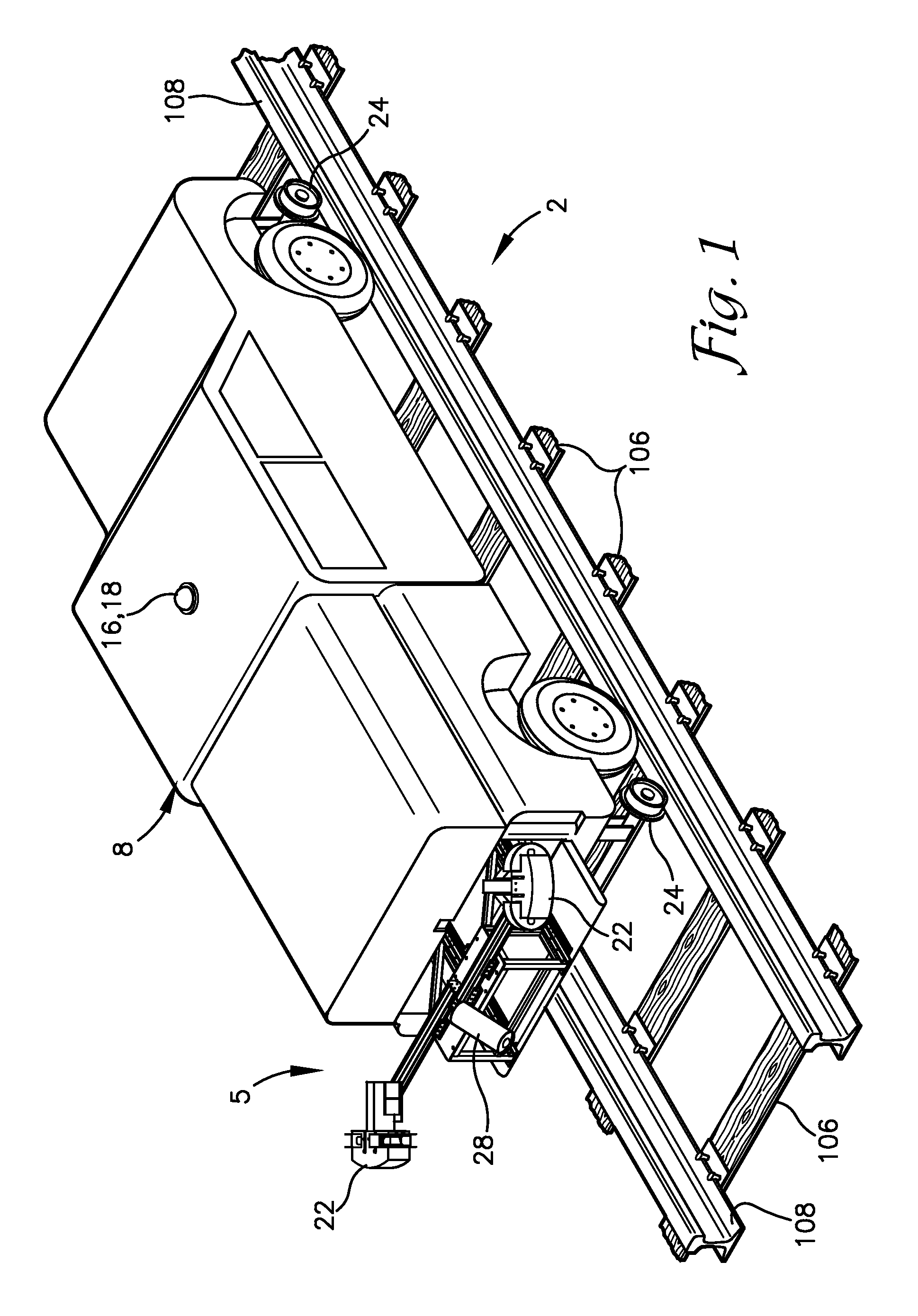
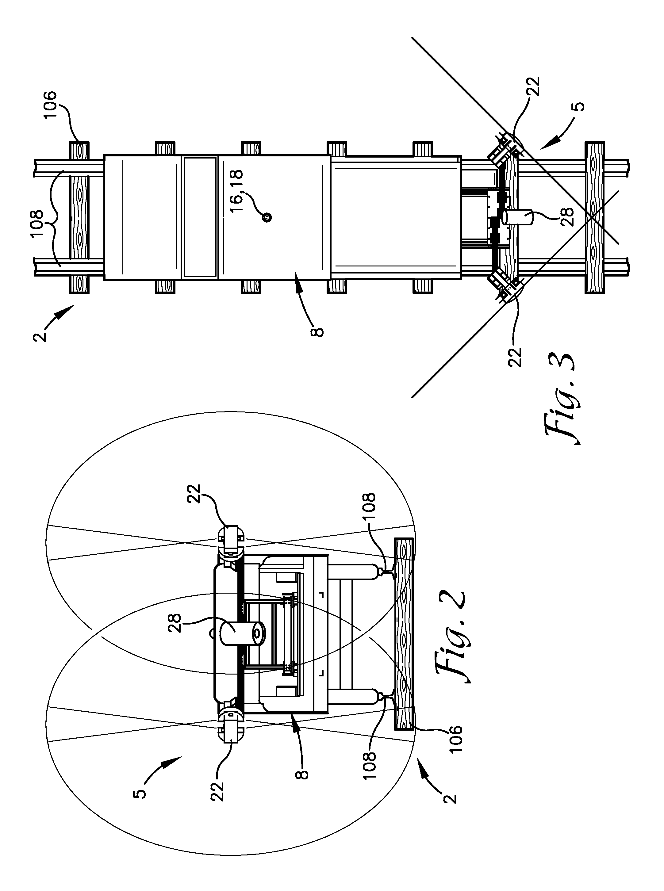
[0036]Referring to the drawings in more detail, the reference number 1 (FIG. 6) generally designates an embodiment of an automated track surveying and ditching or ditch maintenance method according to the present invention. The method 1 generally includes optically scanning along intervals of a section of a railway 2 (FIGS. 7 and 8), deriving data sets representing the cross sectional shape of a ditch 3 at each interval, comparing the existing shape of the di...


PUM


Abstract

A method of surveying a section of a railway to determine amounts of soil to be excavated or added at selected position coordinates of track locations includes moving a survey vehicle along the railway, optically scanning the track structure at selected intervals to obtain optical data points with position coordinates, recording images at the intervals with position coordinates, recording position coordinates of drainage points, processing the optical data points to derive ditch overlays formed by ditch profiles associated with locations along the track and ditch templates, detecting anomalous soil unit weights associated with track locations, reviewing images associated with the locations of the anomalous units, adjusting the ditch overlays as necessary, and loading the adjusted data into a computer of an excavator device for display to guide an excavator operator in reshaping the ditches along the track according to the detected position of the excavator device.

Description

CROSS-REFERENCE TO RELATED APPLICATION[0001]This application claims priority from U.S. Provisional Application, Ser. No. 61 / 605,307 filed Mar. 1, 2012 for AUTOMATED TRACK SURVEYING AND DITCHING, the disclosure of which is incorporated herein by reference.BACKGROUND OF THE INVENTION[0002]1. Field of the Invention[0003]This invention relates generally to railroad maintenance and, more particularly, to methods of surveying railroad track beds in conjunction with position recording and performing track maintenance operations, such as maintenance of drainage ditching along the track bed, based on the survey results.[0004]2. Background & Description of the Related Art[0005]Conventional railroads in the United States and elsewhere are formed by a compacted subgrade, a bed of gravel ballast, wooden cross-ties positioned upon and within the ballast, and parallel steel rails secured to the ties. Variations of construction occur at road and bridge crossings, at switch points, and in other circ...

Claims


Application Information

Patent Timeline
IPC IPC(8): G06K9/00
CPCG06K9/00791G06T2207/30252G06T2207/10016G06T7/001G06V20/56Y02A30/30
Inventor LANDES, NATHAN A.BOUNDS, IVAN E.
Owner HERZOG RAILROAD SERVICES
Why Eureka
Try Eureka