
Envelope Tracking Power Amplifier System with Delay Calibration

Active Publication Date: 2013-09-05
QUANTANCE
View PDF1 Cites 85 Cited by
  • Summary
  • Abstract
  • Description
  • Claims
  • Application Information

AI Technical Summary

Benefits of technology

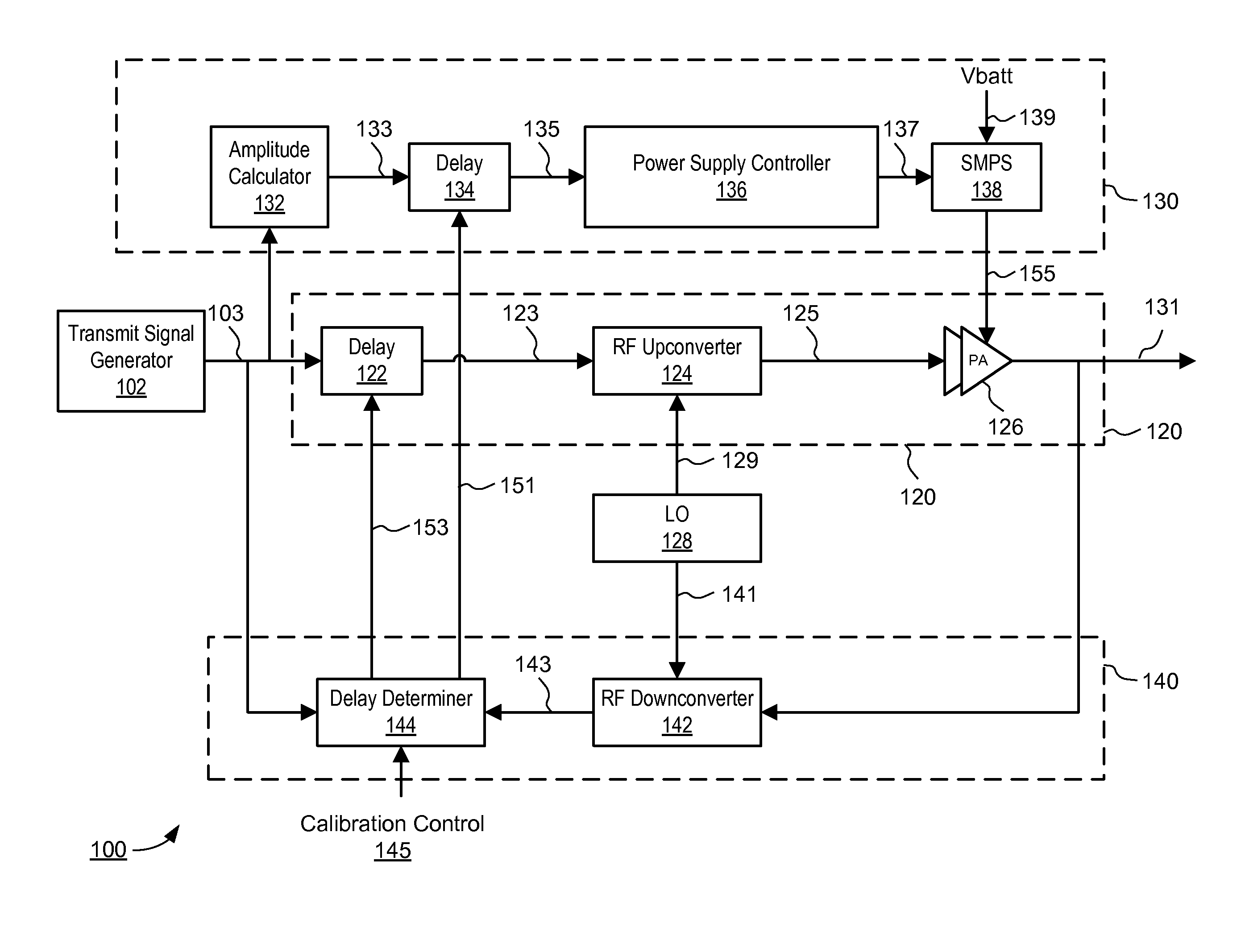
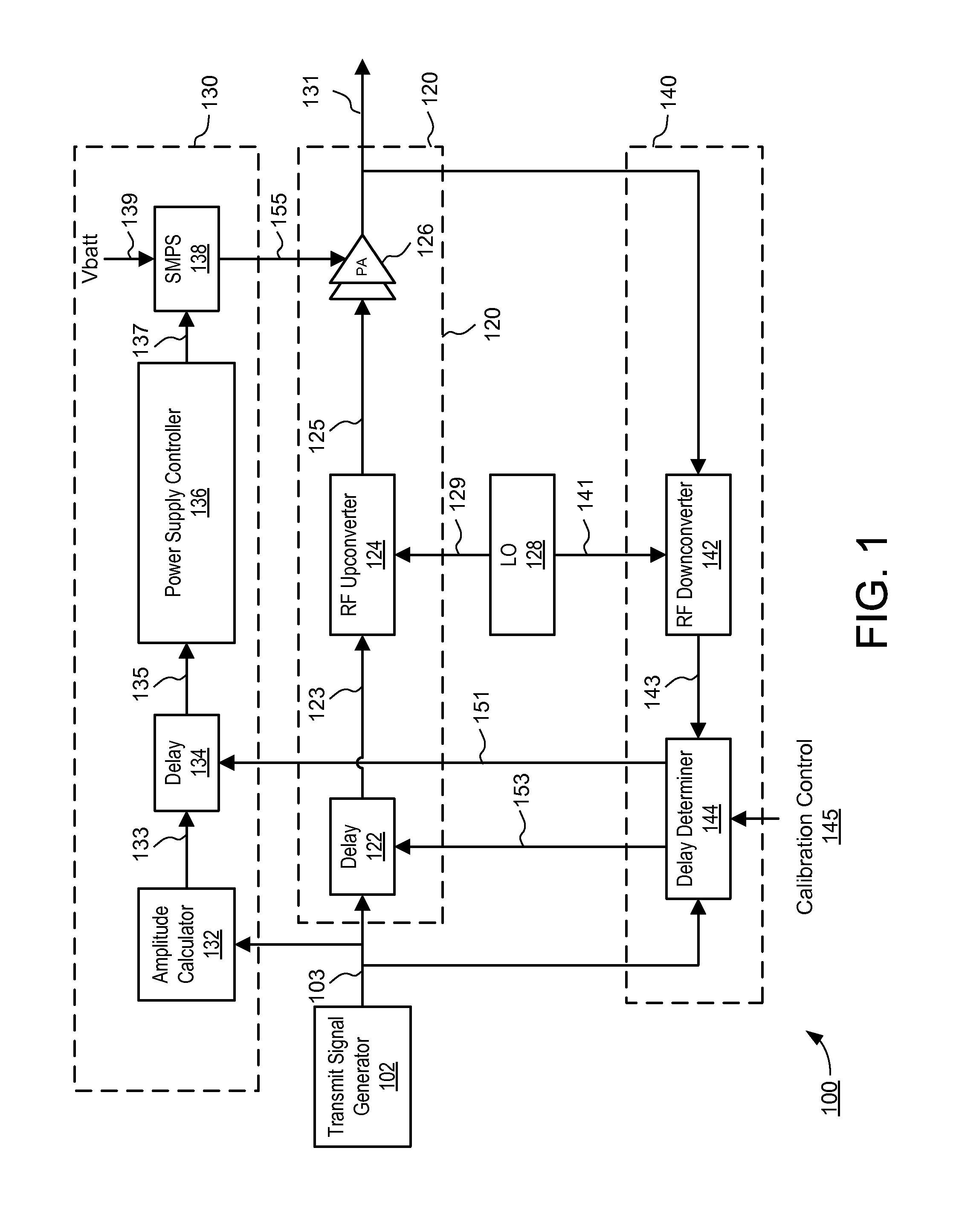
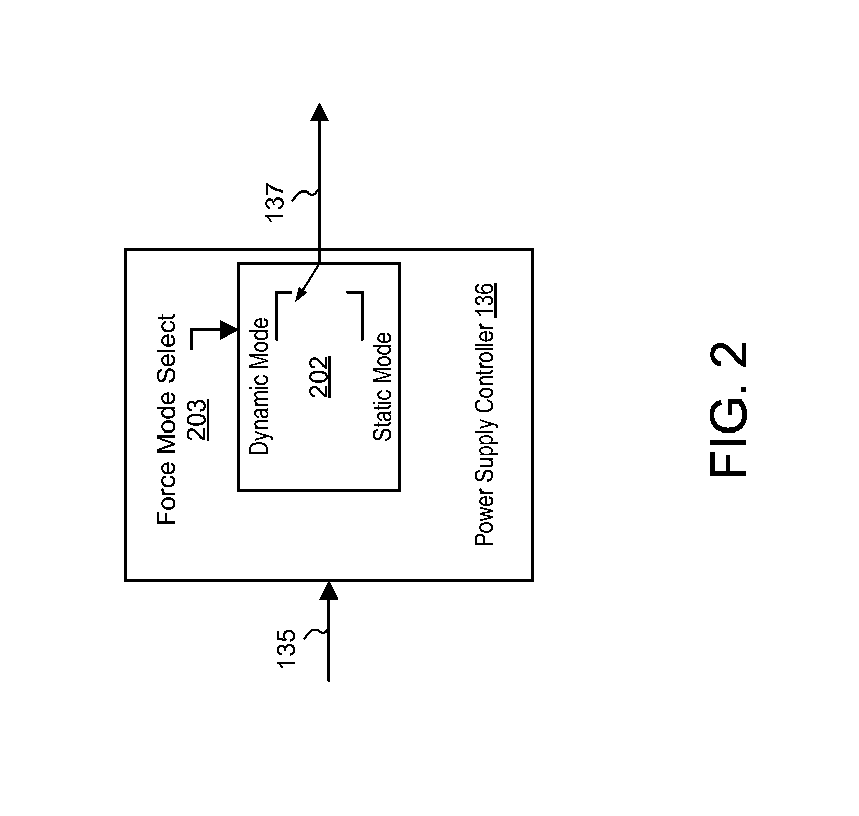
The invention relates to a delay calibration system for an envelope tracking system used in power amplifiers. The system uses a power supply controller to switch between static and dynamic modes based on the amplitude of the input signal. The system measures the delay between the input and output signals and programs a delay block to compensate for any delay mismatches. This results in a more accurate and efficient power amplifier. The technical effect of this invention is to improve the reliability and performance of power amplifiers by compensating for delay mismatches and optimizing the dynamic response of the power supply.

Problems solved by technology

In a conventional ET PA system, varying delays may be present in the RF signal path and the envelope tracking power supply path, thus causing misalignment in the envelope tracking.
This misalignment is undesirable because it causes distortion of the output signal.

Method used


Image

  • Envelope Tracking Power Amplifier System with Delay Calibration
  • Envelope Tracking Power Amplifier System with Delay Calibration
  • Envelope Tracking Power Amplifier System with Delay Calibration

Examples


Embodiment Construction

[0021]The Figures (FIG.) and the following description relate to various embodiments by way of illustration only. It should be noted that from the following discussion, alternative embodiments of the structures and methods disclosed herein will be readily recognized as viable alternatives that may be employed without departing from the principles discussed herein.

[0022]Reference will now be made in detail to several embodiments, examples of which are illustrated in the accompanying figures. It is noted that wherever practicable similar or like reference numbers may be used in the figures and may indicate similar or like functionality. The figures depict various embodiments for purposes of illustration only. One skilled in the art will readily recognize from the following description that alternative embodiments of the structures and methods illustrated herein may be employed without departing from the principles described herein.

[0023]An envelope tracking power amplifier system time...


PUM


Abstract

An envelope tracking power amplifier system time-aligns a supply voltage to an input signal to a power amplifier. The power supply operates in a static mode for low amplitude input signals and operates in a dynamic mode for high amplitude input signals. In the static mode, the power supply produces a substantially constant supply voltage independent of the amplitude of the input signal. In the dynamic mode the power supply produces a dynamically varying envelope tracking supply voltage based on the amplitude of the input signal. A first delay is determined based on portions of the input and output signals captured during static operation of the power supply and a second delay is determined based on portions of the input and output signals captured during dynamic operation. A delay mismatch is estimated based on a difference between the first and second delays.

Description

CROSS REFERENCE TO RELATED APPLICATIONS[0001]This application claims the benefit of U.S. Provisional Application No. 61 / 606,454 entitled “Envelope Tracking Delay Calibration System” to Serge Francois Drogi filed on Mar. 4, 2012, the contents of which are incorporated by reference herein.BACKGROUND[0002]1. Field of Technology[0003]Embodiments disclosed herein relate to an envelope tracking power amplifier system, and more specifically to calibrating delay in an envelope tracking power amplifier system.[0004]2. Description of the Related Arts[0005]In an envelope tracking (ET) power amplifier (PA) system, a power supply supplies a dynamically changing supply voltage to the PA. The supply voltage to the PA adjusts as the amplitude of the radio frequency (RF) signal to the PA changes such that the PA operates at or near peak efficiency for the given instantaneous output power requirements.[0006]In a conventional ET PA system, varying delays may be present in the RF signal path and the en...

Claims


Application Information

Patent Timeline
IPC IPC(8): H04B1/04H03F3/24
CPCH04B1/0475H03F3/245H04B2001/0416H03F2200/102H03F1/0227H03F1/0205H03F3/19H03F3/211H03F2200/451
Inventor DROGI, SERGE FRANCOIS
Owner QUANTANCE
Learn More