
Tire uniformity testing system

a technology of uniformity and testing system, applied in vehicle tyre testing, vehicles, instruments, etc., can solve the problems of time-consuming and laborious rim replacement, and achieve the effect of facilitating the replacement of rim sets

Active Publication Date: 2013-09-12
MICRO POISE MEASUREMENT SYST
View PDF11 Cites 23 Cited by
  • Summary
  • Abstract
  • Description
  • Claims
  • Application Information

AI Technical Summary

Benefits of technology

The present invention provides a new and improved tire uniformity testing system that includes a method and apparatus for automatically changing rim sets when the size of the tires being tested changes. The invention enables quick and easy replacement of rim sets, reducing downtime for the tire uniformity testing machine and increasing its throughput. This is achieved by using a rim set assembly with a bracket for holding a pair of rims, which can be easily replaced at a testing station. The disclosed method and apparatus make it simple for operators to install and remove rims from spindles, with minimal effort required.

Problems solved by technology

The changing of rims can be time-consuming and strenuous.

Method used


Image

  • Tire uniformity testing system
  • Tire uniformity testing system
  • Tire uniformity testing system

Examples


Embodiment Construction

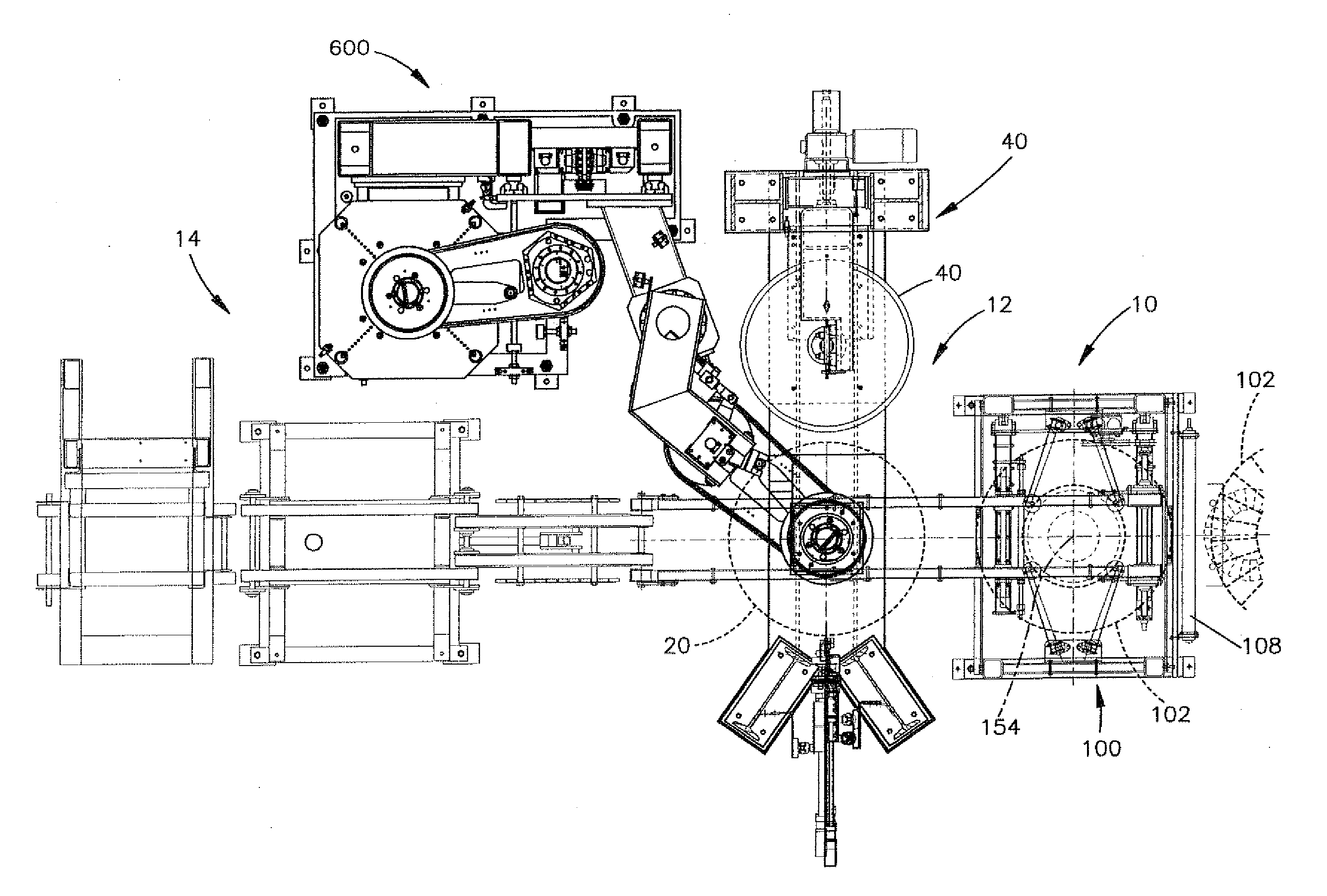
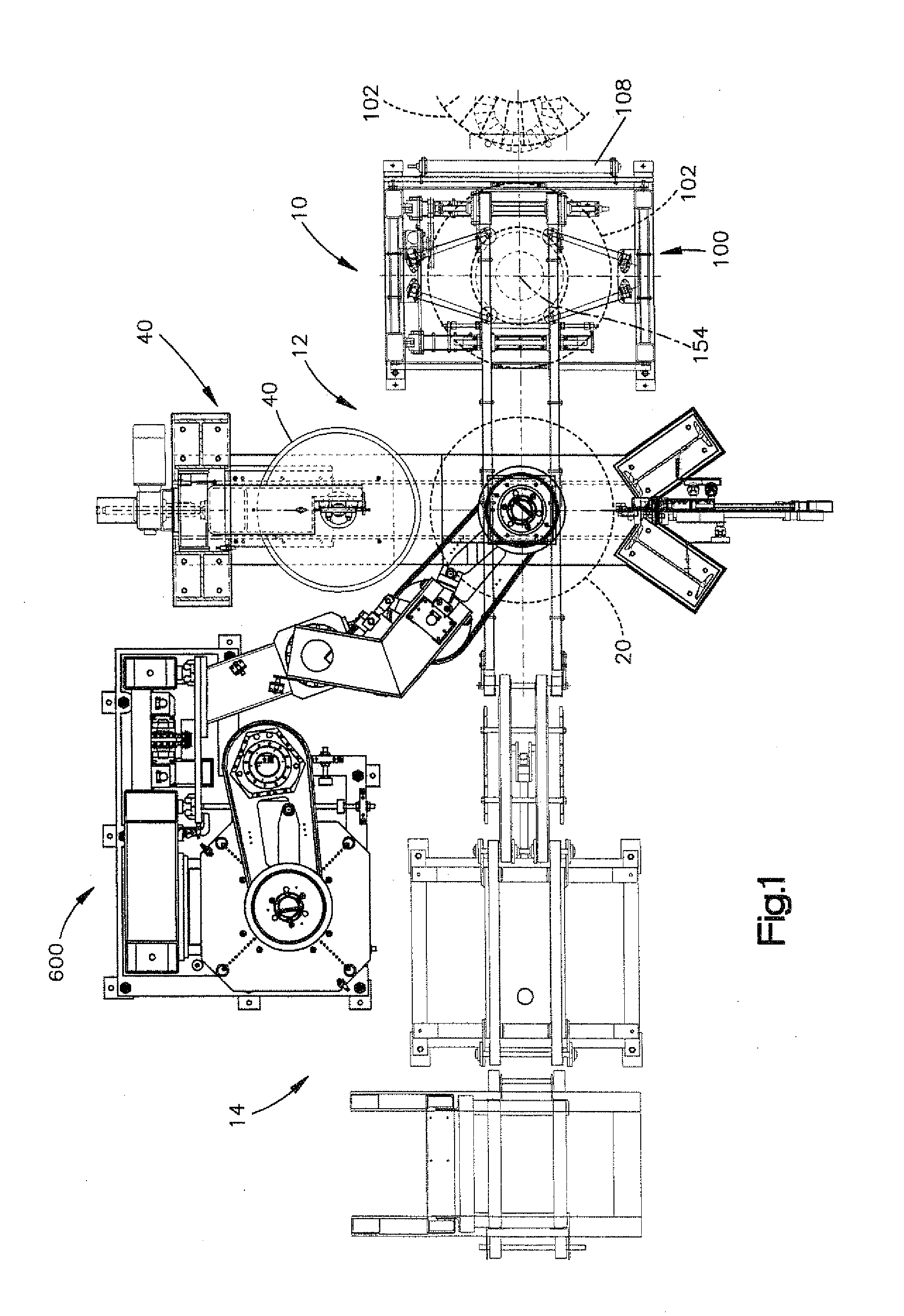
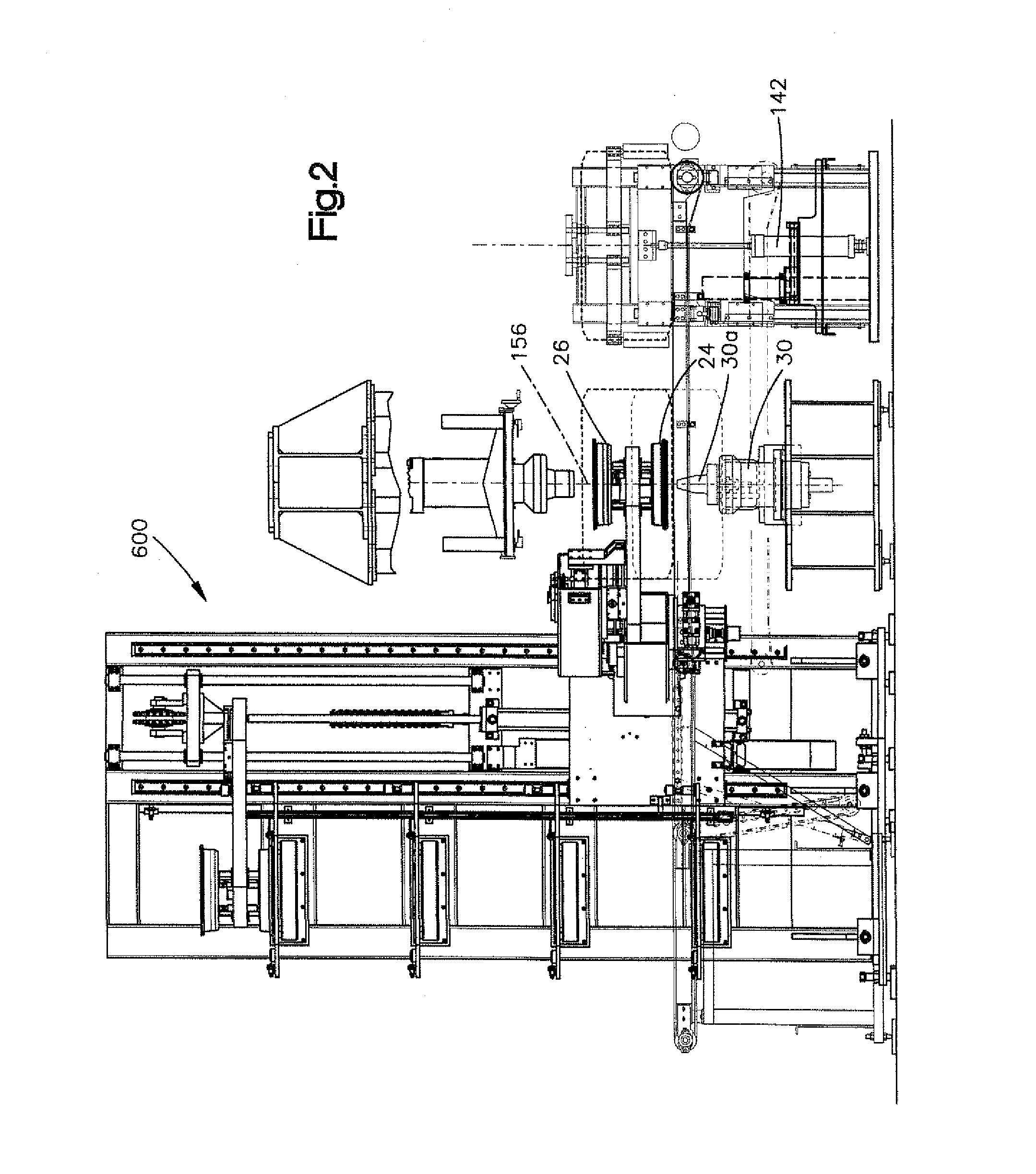
[0035]FIGS. 1 and 2 show the overall construction of a tire uniformity testing machine that includes an automatic rim change apparatus 600 constructed in accordance with a preferred embodiment of the invention. The tire uniformity machine of the type shown in FIGS. 1 and 2 is used to check tires for uniformity prior to shipment or prior to installation on a vehicle. The system shown in FIGS. 1 and 2 is virtually entirely automatic and receives tires from a centering station 10 and delivers tested tires to a delivery station 14.

[0036]FIG. 1 illustrates, in plan view, the overall arrangement of a tire testing system constructed in accordance with the preferred embodiment of the invention. Major subsystems include an inlet conveyer 10; a testing station 12; and, an exit module 14 which may include a marking station, as well as a tire sorting mechanism. A tire positioned at the testing station 12 is tested and optionally ground to adjust its roundness, uniformity and / or other desired ph...


PUM

PropertyMeasurementUnit
angle of rotationaaaaaaaaaa
relative rotationaaaaaaaaaa
movementaaaaaaaaaa

Abstract

An apparatus for changing rim sets at a testing station of a tire uniformity testing system that includes a storage unit for storing a plurality of rim set assemblies. A transfer arm is reciprocally movable and includes a gripper mechanism for gripping a rim set assembly and moving it from a storage position to a position at which rims forming part of the rim set assembly are aligned with opposed spindles at the testing station. The rim set assembly includes a bracket having structure engageable by the transfer arm and at least one of the rims forming part of the assembly includes a locking member rotatable between a first position and a second position. The bracket includes a structure for immobilizing the rim to inhibit relative rotation between the rim and the bracket and further includes a lever mechanism for moving the locking member from its first position to its second position in order to engage retaining members forming part of the bracket. The lever mechanism moves the locking member from its second position to its first position when the rim is aligned with an associated spindle in order to engage other retaining members forming part of the spindle. The rim is released from the bracket as the locking member moves to engage the other retaining members. After release, the bracket moves to a remote position spaced from the testing station. To remove the rim sets, the steps for attaching rims to the spindles are reversed in order to release the rims from the spindles while simultaneously engaging the bracket. The resulting rim set assembly is moved to a remote position defined by a storage unit that stores a plurality of rim set assemblies. The disclosed locking member and associated rim can be used to facilitate the manual installation of a test rim to a spindle.

Description

RELATED APPLICATIONS[0001]This application claims priority from U.S. Provisional Application No. 61 / 416,575, filed Nov. 23, 2010, the entirety of which is incorporated herein by reference.TECHNICAL FIELD[0002]The present invention relates generally to tire uniformity testing systems and, in particular, to a method and apparatus for automatically changing rim sets on a tire uniformity machine.BACKGROUND ART[0003]Tire uniformity testing systems are used throughout the tire manufacturing and automotive industries. These machines check tire uniformity parameters on manufactured tires. Many of the testing functions are fully automated. In particular, tires are fed by a conveyor to a tire testing station where they are clamped between tire rims, inflated and then placed in rolling contact with a loadwheel. At the conclusion of the test, the rims are separated and the tires are delivered to an exit location by another conveyor.[0004]The rims that are used to clamp the tires at the testing ...

Claims


Application Information

Patent Timeline
Patent Type & Authority Applications(United States)
IPC IPC(8): G01M17/02B60C25/00
CPCG01M17/021B60C25/002Y10T29/49826Y10T29/49815G01M17/02B60C19/00
Inventor WOLLBRINCK, JAMESMATUSZNY, RICHARD R.CARGOULD, BARRYWILLIAMS, PETER
Owner MICRO POISE MEASUREMENT SYST
Learn More