Flat heap pipe structure

a technology of heat pipe and heap, which is applied in the direction of indirect heat exchangers, lighting and heating apparatus, and reinforcement means, etc., can solve the problems of reducing the service life of the heat dissipating device comprised of aluminum heat sinks and fans, affecting the service life of the heat dissipating device, and affecting the operation of the cpu with increased clock speed, etc., and achieves the effect of increasing the strength

Active Publication Date: 2013-09-12
COOLER MASTER CO LTD
View PDF14 Cites 19 Cited by
  • Summary
  • Abstract
  • Description
  • Claims
  • Application Information

AI Technical Summary

Benefits of technology

[0011]For advantages, the main walls of the flat heat pipe structure provide additional strength for the annular tubing during the flattening process. After disposing the support member inside the heat pipe structure, the heat pipe structure ca

Problems solved by technology

The conventional heat dissipating device comprised of an aluminum heat sink and a fan can no longer accommodate the operational demand of today's CPU with increased clock speed.
However, the conventional support member typically is very rigid and makes the tubing very difficult to bend.
One of the c

Method used


Image

  • Flat heap pipe structure
  • Flat heap pipe structure
  • Flat heap pipe structure

Examples


Embodiment Construction

[0021]To attain further understanding of the objectives, structural features, and functions of the instant disclosure, please refer to the detailed descriptions provided hereinbelow.

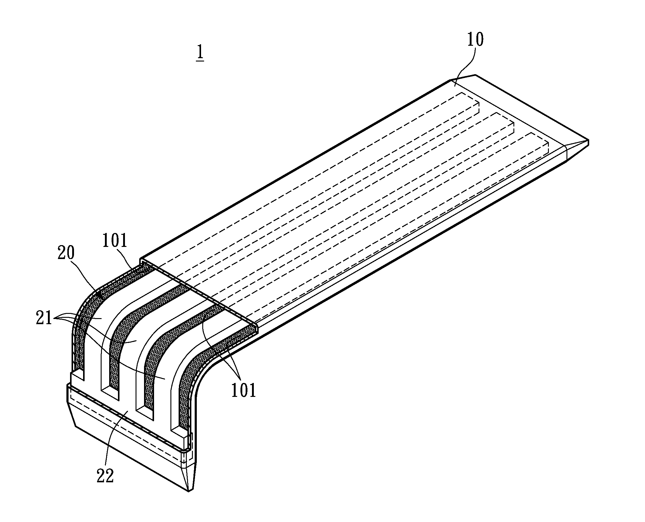
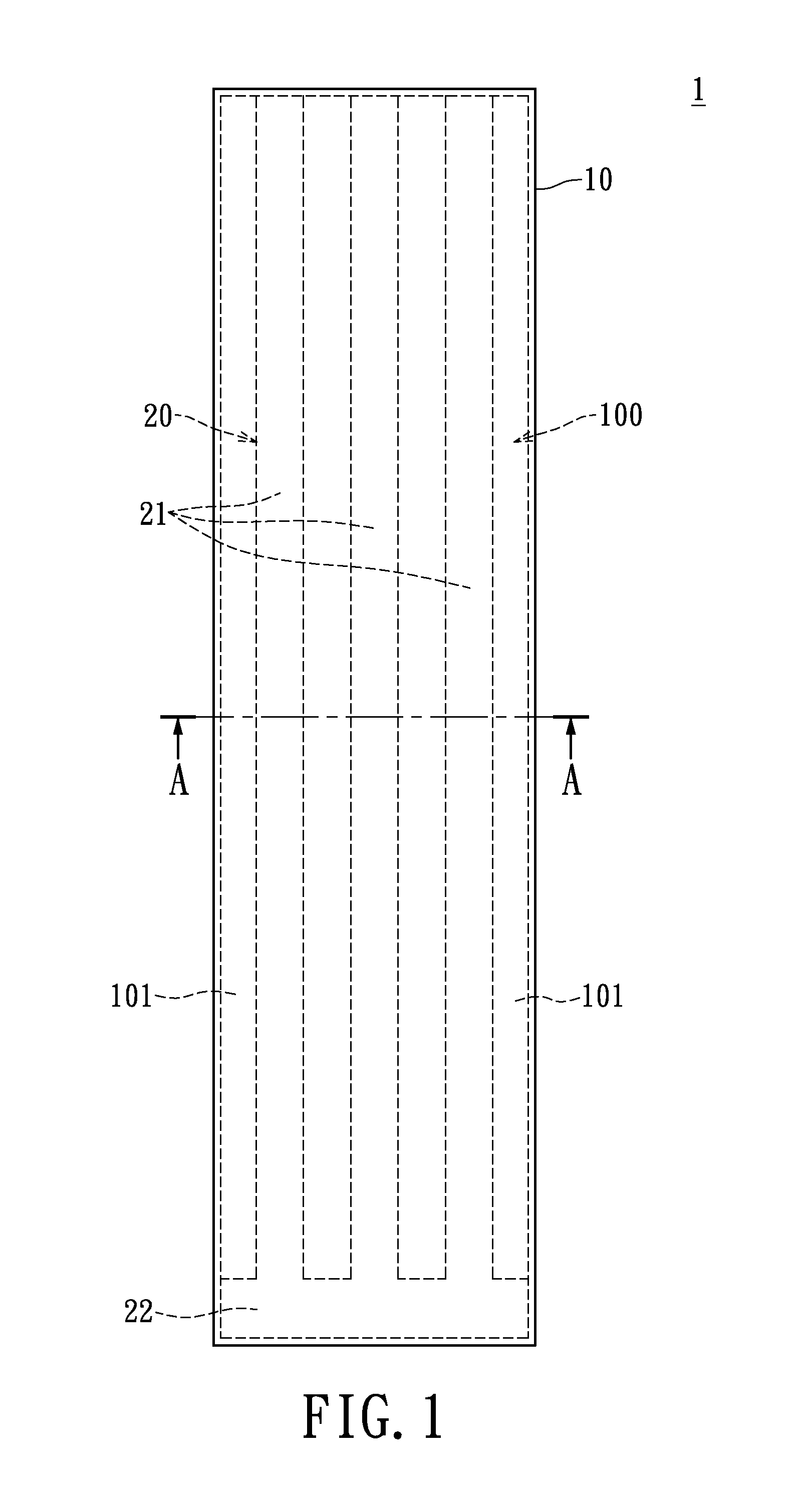
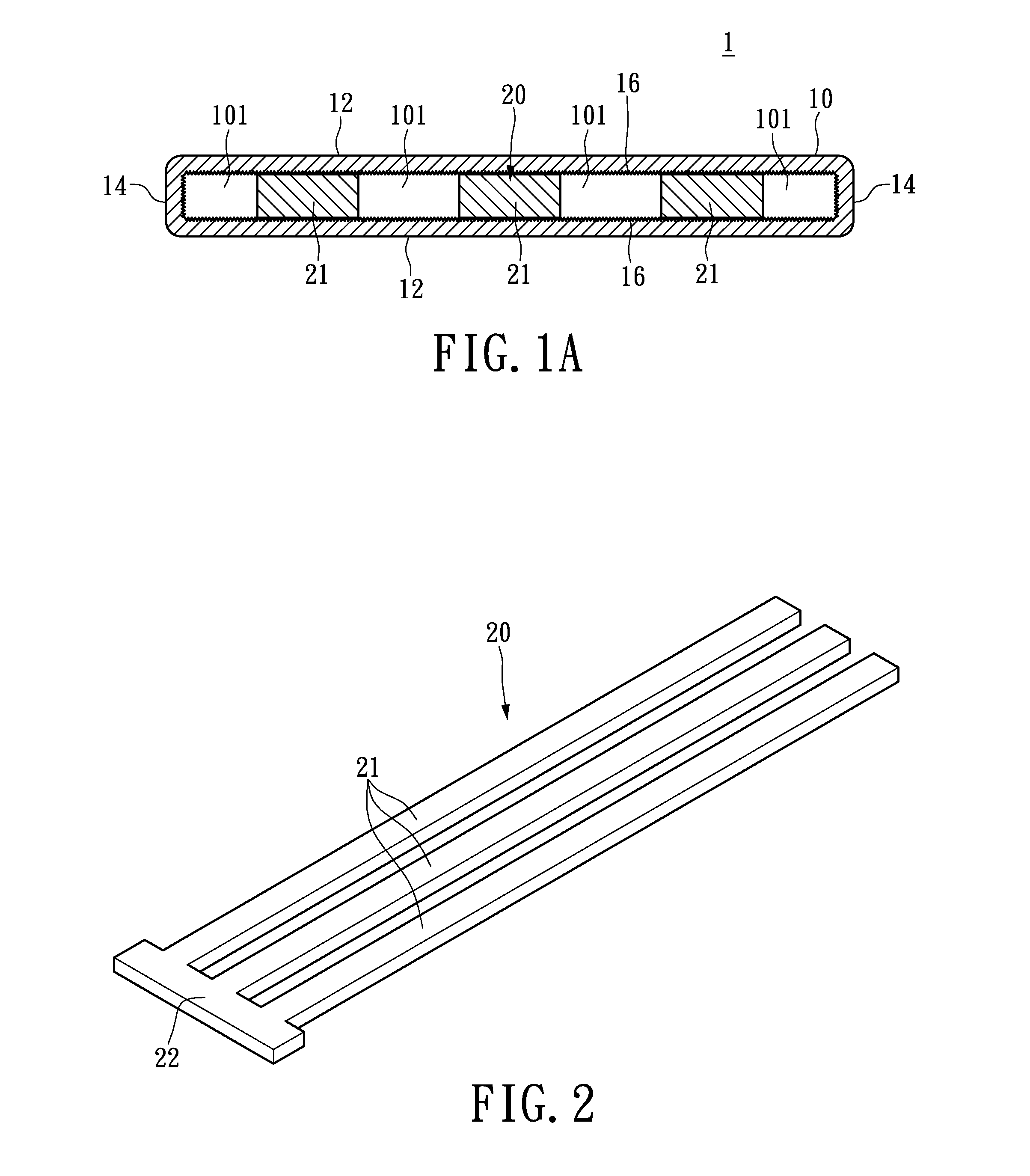
[0022]FIG. 1 shows a top view of a flat heat pipe structure 1 of the instant disclosure, and FIG 1A shows a cross-sectional view thereof taken along line AA in FIG. 1. The flat heat pipe structure 1 comprises a flat tubing 10 and a support member 20 disposed therein. The flat tubing 10 is made with material with excellent thermal conductivity and malleability such as aluminum, aluminum alloy, copper, copper alloy, etc. The flat tubing 10 is manufactured by flattening an annular tubing. For the instant embodiment, the flat tubing 10 is elongated and has a strip-like shape. Alternatively, the flat tubing 10 may be rectangular with a plate-like shape, where the exact structural shape of the flat tubing 10 is not restricted.

[0023]The flat tubing 10 is defined by two opposed main walls 12 and two opposed conn...


PUM


Abstract

The instant disclosure relates to a flat heat pipe structure, which includes a flat tubing and a support member. The flat tubing has two opposed main walls and two opposed connecting walls connected thereto. The main and connecting walls cooperatively define an internal space. The inner surfaces of the flat tubing are covered with a capillary structure. The support member is disposed in the internal space of the flat tubing and has at least one support arm. The support arm extends in the longitudinal direction of the flat tubing. The support arm has two opposed surfaces abutting to the capillary structure of the main walls.

Description

BACKGROUND OF THE INVENTION[0001]1. Field of the Invention[0002]The instant disclosure relates to a flat heat pipe structure; more particularly, to a heat-moving flat heat pipe structure having internal support member.[0003]2. Descriptions of Related Art[0004]As the speed of a central processing unit (CPU) increases, more heat is given off by the CPU. The conventional heat dissipating device comprised of an aluminum heat sink and a fan can no longer accommodate the operational demand of today's CPU with increased clock speed. To address this issue, more powerful and capable heat pipes and vapor chambers have been developed to work with the heat sink.[0005]Due to adhesive characteristic of the porous capillary structure of the heat pipe and pressure differential across its walls, a support member is required to be disposed in the heat pipe, such that the tubing has enough supporting strength after being flattened. However, the conventional support member typically is very rigid and m...

Claims


Application Information

Patent Timeline
IPC IPC(8): F28D15/04
CPCF28D15/04F28D15/0233F28F2225/04F28D15/046
Inventor LIU, LEILEIWANG, XUEMEI
Owner COOLER MASTER CO LTD
Why Eureka
Try Eureka