Vanity mirror

a technology of mirrors and mirrors, applied in the field of mirrors, can solve the problems of poor quality reflective surfaces, harsh light sources, distortion of reflected images, etc., and achieve the effect of constant light emitted

Active Publication Date: 2013-09-12
SIMPLEHUMAN
View PDF9 Cites 45 Cited by
  • Summary
  • Abstract
  • Description
  • Claims
  • Application Information

AI Technical Summary

Benefits of technology

[0009]Certain aspects of this disclosure are directed toward a minor assembly. The minor assembly can include a mirror coupled with the housing portion, and a light source disposed at a periphery of the mirror. The mirror assembly can include a light path, such as a light pipe, having a length and positioned around at least a portion of the periphery of the mirror. The minor assembly can include a light scattering region, such as a plurality of light scattering elements disposed along the length of the light pipe. The light scattering elements can have a pattern density that varies depending, at least in part, on the distance along the light path from the light source. The light scattering elements can be configured to encourage a portion of the light impacting the light scattering elements to be emitted out of the light path along a desired portion of the length of the light path. The amount of light scattering elements on the light path can vary depending, at least in part, on the distance along the light path from the light source. In certain embodiments, the pattern density can be less dense in a region generally adjacent the light source and more dense in a region spaced away from, or generally opposite from, the light source along the periphery of the minor, thereby scattering the light to a greater degree as the intensity of the light diminishes further from the light source, and facilitating a substantially constant amount of light emitted along the length of the light pipe.

Problems solved by technology

Many vanity minors distort the reflected image because of, for example, poor quality reflective surfaces, harsh light sources, and / or uneven distribution of light.
Additionally, the light sources of conventional vanity mirrors are typically energy inefficient.
Further, the light sources of conventional vanity mirrors are not adjustable or are difficult to effectively adjust.

Method used


Image

  • Vanity mirror
  • Vanity mirror
  • Vanity mirror

Examples


Embodiment Construction

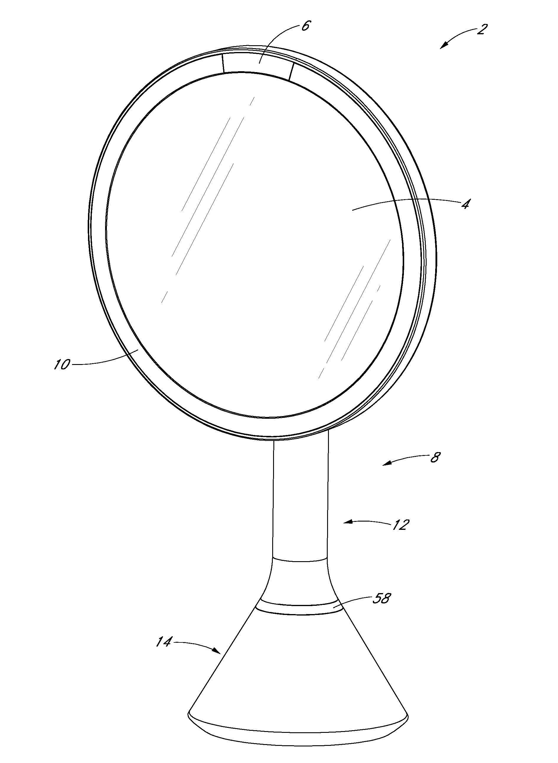
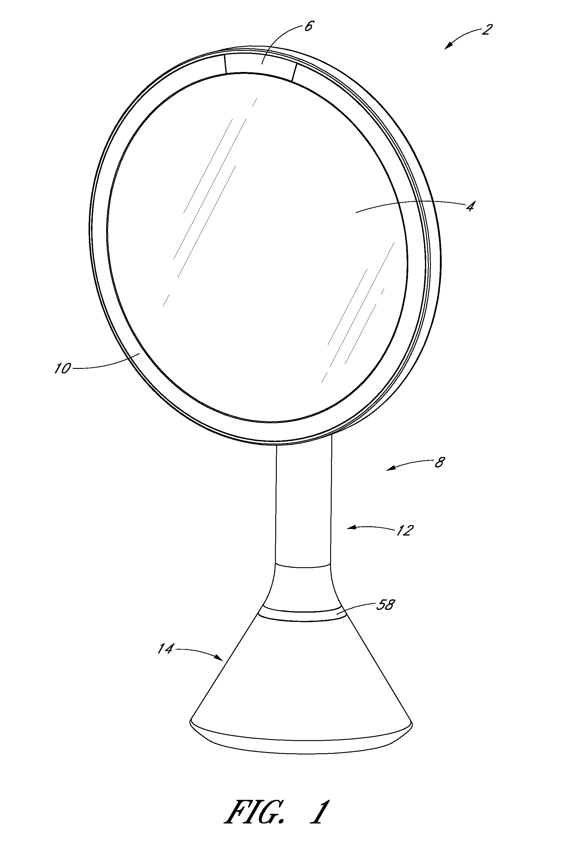
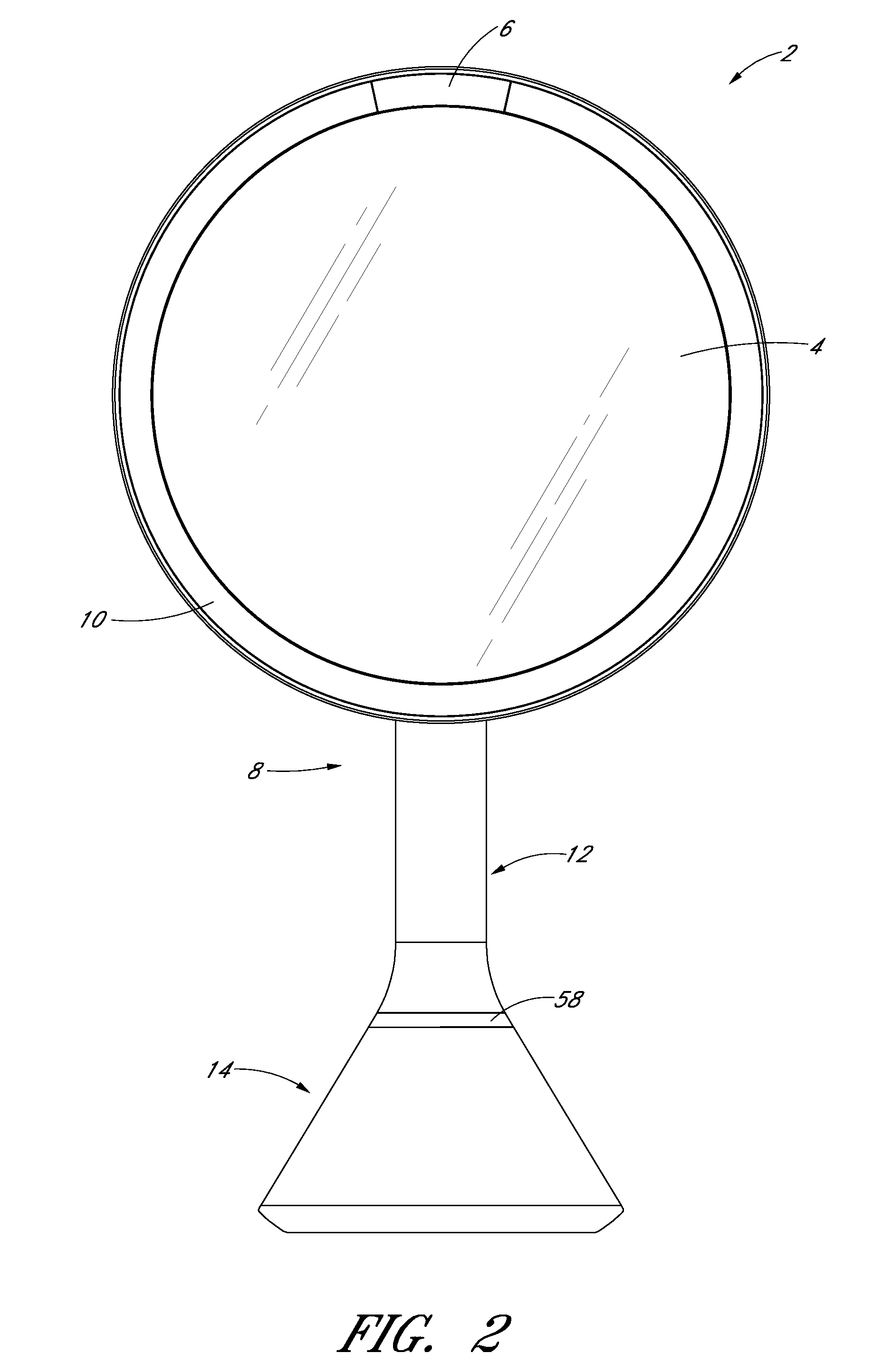
[0034]Certain embodiments of a minor assembly are disclosed in the context of a portable, free-standing vanity minor, as it has particular utility in this context. However, the various aspects of the present disclosure can be used in many other contexts as well, such as wall-mounted minors, mirrors mounted on articles of furniture, automobile vanity minors (e.g., mirrors located in sun-visors), and otherwise. None of the features described herein are essentially or indispensible. Any feature, structure, or step disclosed herein can be replaced with or combined with any other feature, structure, or step disclosed herein, or omitted.

[0035]As shown in FIGS. 1-7, the minor assembly 2 can include a housing portion 8 and a visual image reflective surface, such as a mirror 4. The housing portion 8 can include a support portion 20, a shaft portion 12, and / or a base portion 14. The housing portion 8 can also include a pivot portion 16 connecting the support portion 20 and the shaft portion 1...


PUM

PropertyMeasurementUnit
poweraaaaaaaaaa
color rendering indexaaaaaaaaaa
focal lengthaaaaaaaaaa

Abstract

A minor assembly can include a housing, a mirror, and a light source. In certain embodiments, the mirror includes a light pipe configured to emit a substantially constant amount of light along a periphery of the mirror. In some embodiments, the mirror assembly includes a sensor assembly. The sensor assembly can be configured to adjust the amount of emitted light based on the position of a user in relation to the mirror. Certain embodiments of the minor include an algorithm to adjust light based on the position of a user relative to the mirror, the level of ambient light, and/or the activation of different light modes.

Description

CROSS-REFERENCE TO RELATED APPLICATIONS[0001]This present application claims priority benefit under 35 U.S.C. §119(e) to U.S. Provisional Application No. 61 / 608,584, filed Mar. 8, 2012, entitled “VANITY MIRROR ASSEMBLY,” which is hereby incorporated by reference in its entirety.BACKGROUND[0002]1. Field[0003]The present disclosure relates to reflective devices, such as minors.[0004]2. Description of the Related Art[0005]Vanity minors are mirrors that are typically used for reflecting an image of a user during personal grooming, primping, cosmetic care, or the like. Vanity minors are available in different configurations, such as free-standing mirrors, hand-held mirrors, mirrors connected to vanity tables, bathroom wall minors, car minors, and / or minors attached to or produced by electronic screens or devices.[0006]Many vanity minors distort the reflected image because of, for example, poor quality reflective surfaces, harsh light sources, and / or uneven distribution of light. Addition...

Claims


Application Information

Patent Timeline
Patent Type & Authority Applications(United States)
IPC IPC(8): F21V33/00F21V8/00F21V11/00
CPCF21V33/004F21V11/00F21V33/0004Y10T29/49826A47G1/02A45D42/10A47G2200/08G02B6/0096A47G2200/186
Inventor YANG, FRANKWOLBERT, DAVIDSANDOR, JOSEPHCARDENAS, ORLANDOBUSHROE, FREDERICK N.
Owner SIMPLEHUMAN
Why Eureka
Try Eureka