
Dehumidifier

a dehumidifier and heat recovery technology, which is applied in the field of dehumidifiers, can solve the problems of low amount of dehumidification per power consumption, difficulty in raising the temperature of air, etc., and achieve the effects of improving the constitution reducing the power consumption of the heater, and increasing the heat recovery rate of the heat exchanger

Inactive Publication Date: 2009-05-19
AMBIENT CORPORATION
View PDF11 Cites 1 Cited by
  • Summary
  • Abstract
  • Description
  • Claims
  • Application Information

AI Technical Summary

Benefits of technology

[0010]The present invention was made in view of the above-mentioned problem, and an object thereof is to provide a dehumidifier by which the rate of heat recovery by the heat exchanger for recovering heat can be increased, the power consumption of the heater can be decreased, and by which the amount of dehumidification per a power consumption can be promoted.
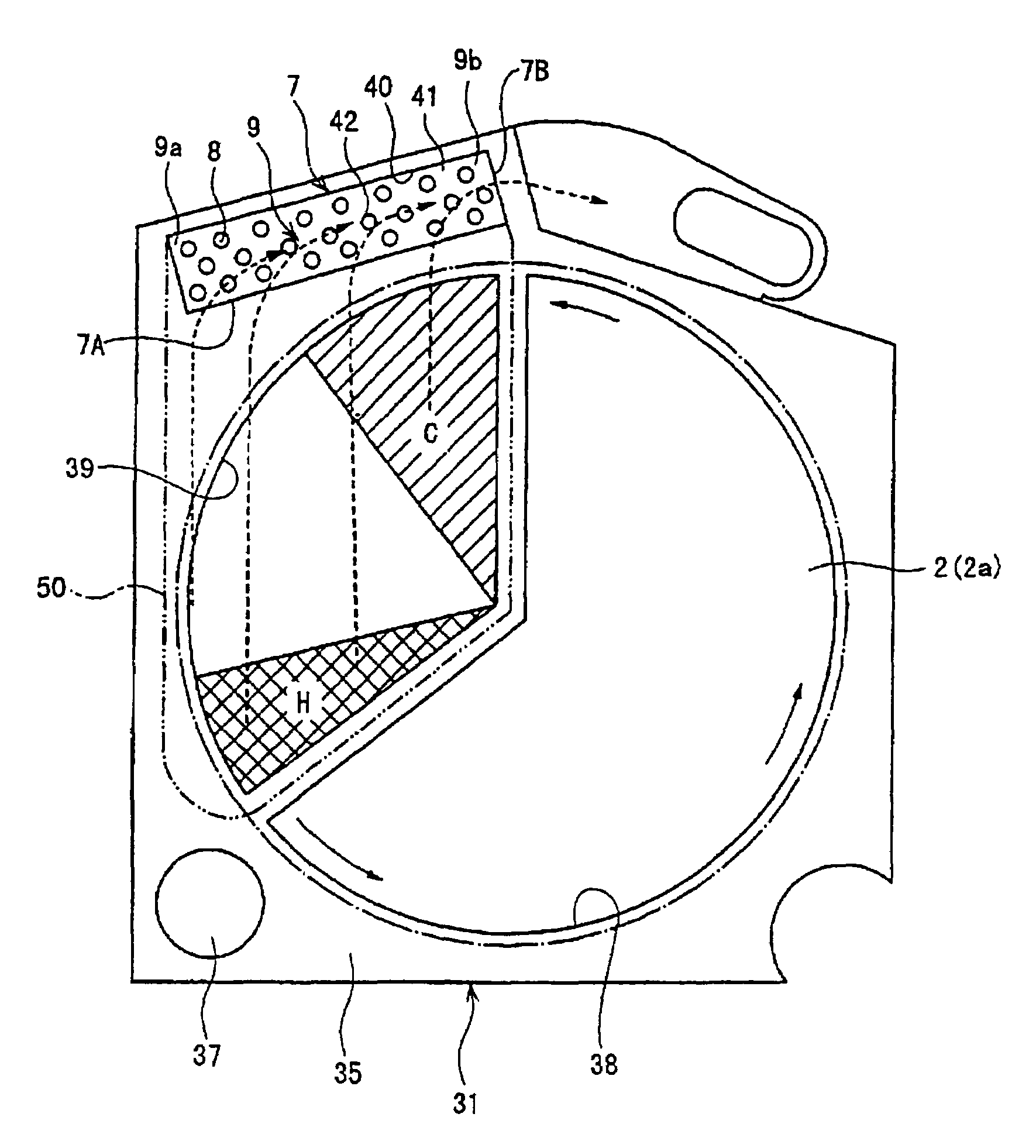
[0011]The present inventor intensively studied to infer that the rate of heat recovery by the heat exchanger for recovering heat can be increased, and in turn, the power consumption of the heater can be decreased and the amount of dehumidification per a power consumption can be promoted, by improving the constitution of the heat exchanger for recovering heat and the direction of rotation of the dehumidification rotor, or by providing a flow guide plate which guides the air for regeneration after passing through the dehumidification rotor to prescribed positions in the heat exchanger for recovering heat so that the relatively hot air for regeneration which passed through the hot region in the dehumidification rotor is made to move in one of the passages in the heat exchanger for recovering heat for a long distance so as to subject the air to heat exchange for a relatively long time, and that the relatively cool air for regeneration which passed through the relatively cool region in the dehumidification rotor is made to move in one of the passages in the heat exchanger for recovering heat for a short distance so as to subject the air to heat exchange for a relatively short time, thereby completing the present invention.
[0026]According to the present invention, as mentioned above, the rate of heat recovery by the heat exchanger for recovering heat may be increased by improving the constitution of the heat exchanger for recovering heat and the direction of rotation of the dehumidification rotor, or by providing a flow guide plate which guides the air for regeneration after passing through the dehumidification rotor to prescribed positions in the heat exchanger for recovering heat so that the relatively hot air for regeneration which passed through the hot region in the dehumidification rotor is made to move in one of the passages in the heat exchanger for recovering heat for a long distance so as to subject the air to heat exchange for a relatively long time, and that the relatively cool air for regeneration which passed through the relatively cool region in the dehumidification rotor is made to move in one of the passages in the heat exchanger for recovering heat for a short distance so as to subject the air to heat exchange for a relatively short time. Therefore, the power consumption by the heater can be decreased and the amount of dehumidification per a power consumption can be increased.

Problems solved by technology

As a result, it is difficult to raise the temperature of the air to be transferred to the heater 5, so that the amount of dehumidification per a power consumption is low, which is problematic.

Method used


Image

  • Dehumidifier
  • Dehumidifier
  • Dehumidifier

Examples


Embodiment Construction

[0035]As mentioned above, the dehumidifier according to the present invention is characterized in that the rate of heat recovery by the heat exchanger for recovering heat is increased by improving the constitution of the heat exchanger for recovering heat (since the main purpose of this heat exchanger is to heat the air for regeneration before the regeneration of the dehumidification rotor by recovering heat from the air for regeneration after regeneration of the dehumidification rotor, this heat exchanger is called “heat exchanger for recovering heat” for convenience. For short, this heat exchanger may also be called “first heat exchanger”) and the direction of rotation of the dehumidification rotor, or by providing a flow guide plate which guides the air for regeneration after passing through the dehumidification rotor to prescribed positions in the heat exchanger for recovering heat so that the relatively hot air for regeneration which passed through the hot region in the dehumid...


PUM


Abstract

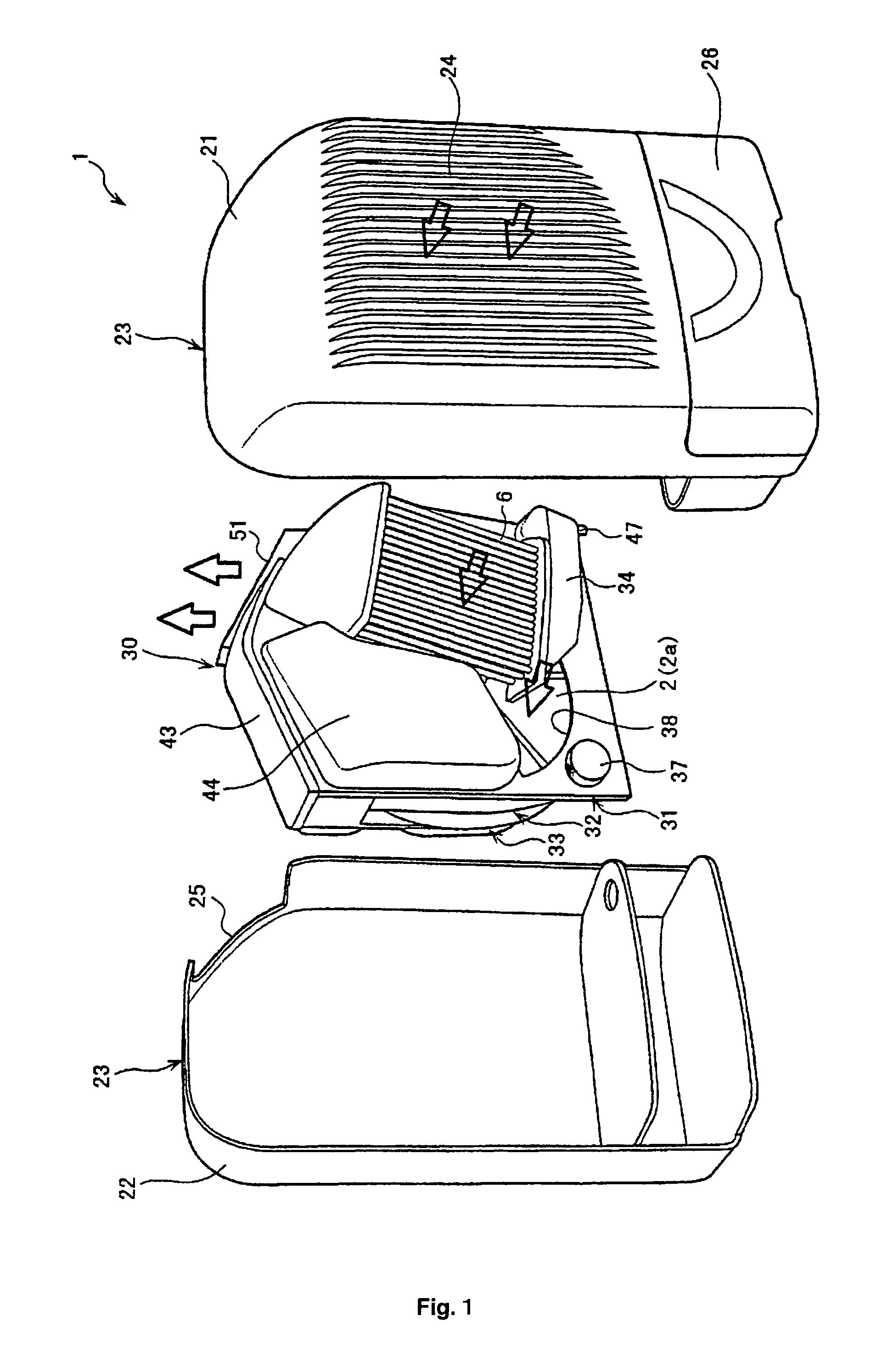
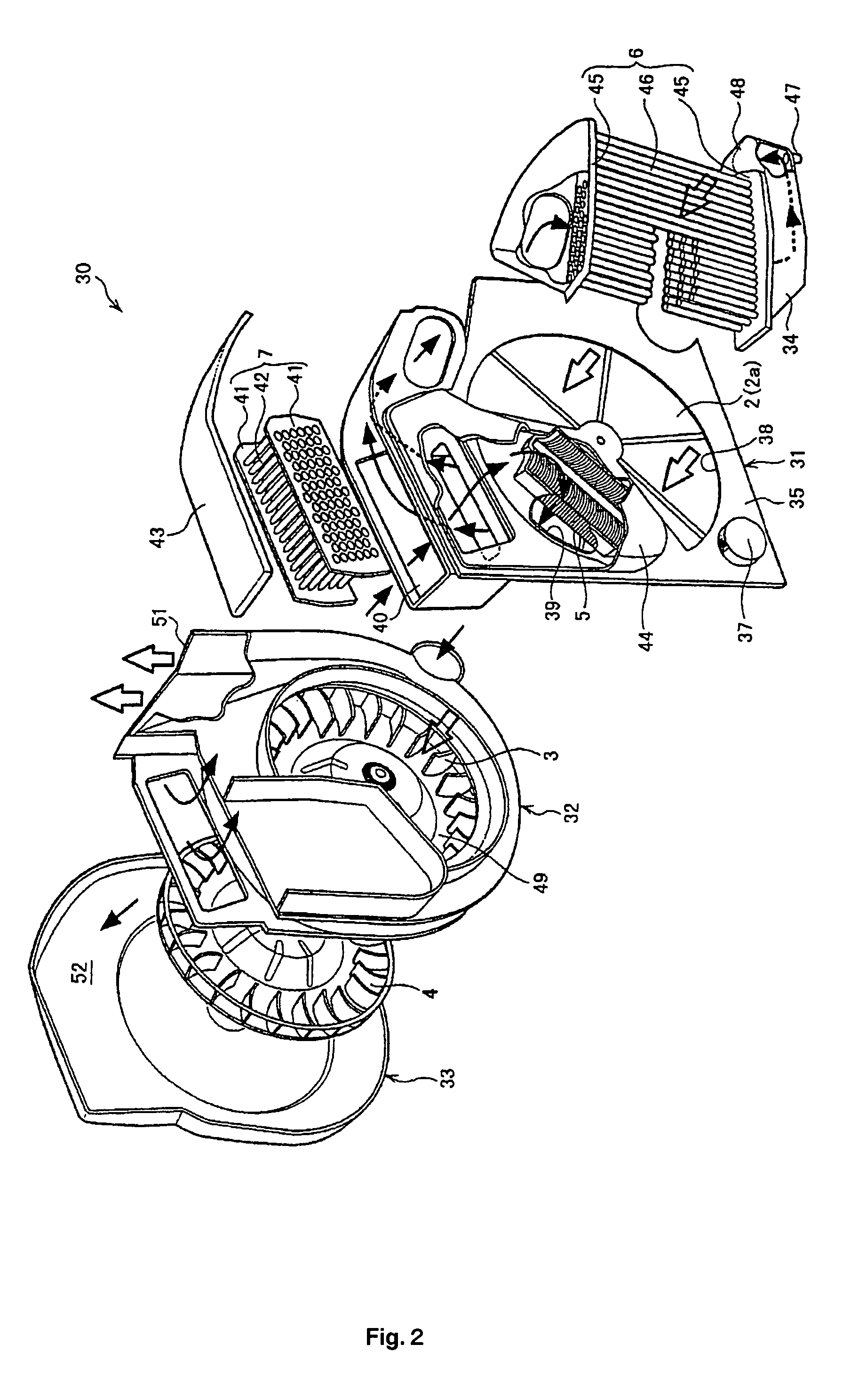
A dehumidifier by which the rate of heat recovery by the heat exchanger for recovering heat can be increased, the power consumption of the heater can be decreased, and by which the amount of dehumidification per a power consumption can be promoted, is disclosed. The dehumidifier 1 comprises a rotor case 31 harboring a dehumidification rotor 2 rotatably and drivably mounted therein, having an opening for dehumidification 38 through which air to be dehumidified passes, and having an opening for regeneration 39 through which air for regeneration passes; a heater 5 for heating the air for regeneration before passing through the opening for regeneration; a heat exchanger for recovering heat 7 which transfers heat of the air for regeneration passing through the second passage section to the air for regeneration passing through the first passage section; a dehumidification passage X harboring a dehumidification fan 3; and a regeneration passage Y harboring a regeneration fan 4. The direction of rotation of the dehumidification rotor 2 is set such that the air for regeneration which passed through posterior area C of the dehumidification rotor flows into downstream portion in the second passage section, and that the air for regeneration which passed through anterior area H of the dehumidification rotor flows into upstream portion in the second passage section.

Description

TECHNICAL FIELD[0001]The present invention relates to a dehumidifier having a dehumidification rotor and a heat exchanger for recovering heat.BACKGROUND ART[0002]A dehumidifier 1 comprising a rotatably and drivably mounted disk-shaped dehumidification rotor, as shown in FIG. 6, for example, is known (e.g., U.S. Pat. No. 6,083,304). The dehumidifier 1 comprises a passage for dehumidification X through which air to be dehumidification is introduced into the dehumidifier 1 from outside by a dehumidification fan 3 so as to dehumidify the air by passing through a dehumidification rotor 2, and through which the dehumidified air is discharged to outside; and a passage for regeneration Y through which air for regeneration for regenerating the dehumidification rotor 2 is circulated in the dehumidifier 1.[0003]This passage for regeneration Y comprises a regeneration fan 4 for circulating the air for regeneration in a closed circuit, a heater 5 for heating the air for regeneration before passi...

Claims


Application Information

Patent Timeline
Patent Type & Authority Patents(United States)
IPC IPC(8): F25D23/00F24F1/02F24F3/14F24F3/147
CPCF24F3/1423F24F2003/1464F24F2203/1012F24F2203/1084F24F2203/1032F24F2203/106F24F2203/1068F24F2203/1016Y02E30/10F24F3/14
Inventor IKE, HIDETOSHI
Owner AMBIENT CORPORATION
Learn More