Insulated wire and coil formed by using the same

a technology of insulated wire and coil, which is applied in the direction of plastic/resin/waxes insulators, organic insulators, electrical appliances, etc., can solve the problems of insufficient flexibility and damage such as cracks, and achieve the effect of improving the space factor of winding and preventing damag

Inactive Publication Date: 2013-09-19
HITACHI METALS LTD
View PDF4 Cites 9 Cited by
  • Summary
  • Abstract
  • Description
  • Claims
  • Application Information

AI Technical Summary

Benefits of technology

[0019]According to embodiments of the invention, an insulated wire can be provided that is capable of improving a space factor of winding, and preventing an occurrence of damage such as crack in the insulating film during a bending process, as well as a coil formed by using the insulated wire.

Problems solved by technology

As the insulated wires disclosed in JP-B-2936895 and JP-A-2007-270074, in case that an insulating film in which the resin skeleton of the polyamideimide resin configured to become rigid is used, the insulating film is enhanced in abrasion resistance, on the other hand, it becomes insufficient in flexibility.
If the flexibility of the insulating film is insufficient, during a bending process such as an edgewise bend processing after elongation in which the insulating film is deformed due to severe processing stress, the insulating film cannot follow the deformation, thus damage such as crack may occur therein.

Method used


Image

  • Insulated wire and coil formed by using the same
  • Insulated wire and coil formed by using the same
  • Insulated wire and coil formed by using the same

Examples


embodiments

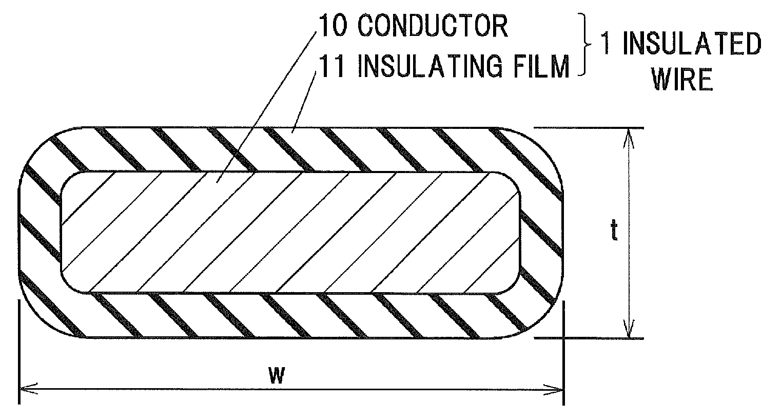
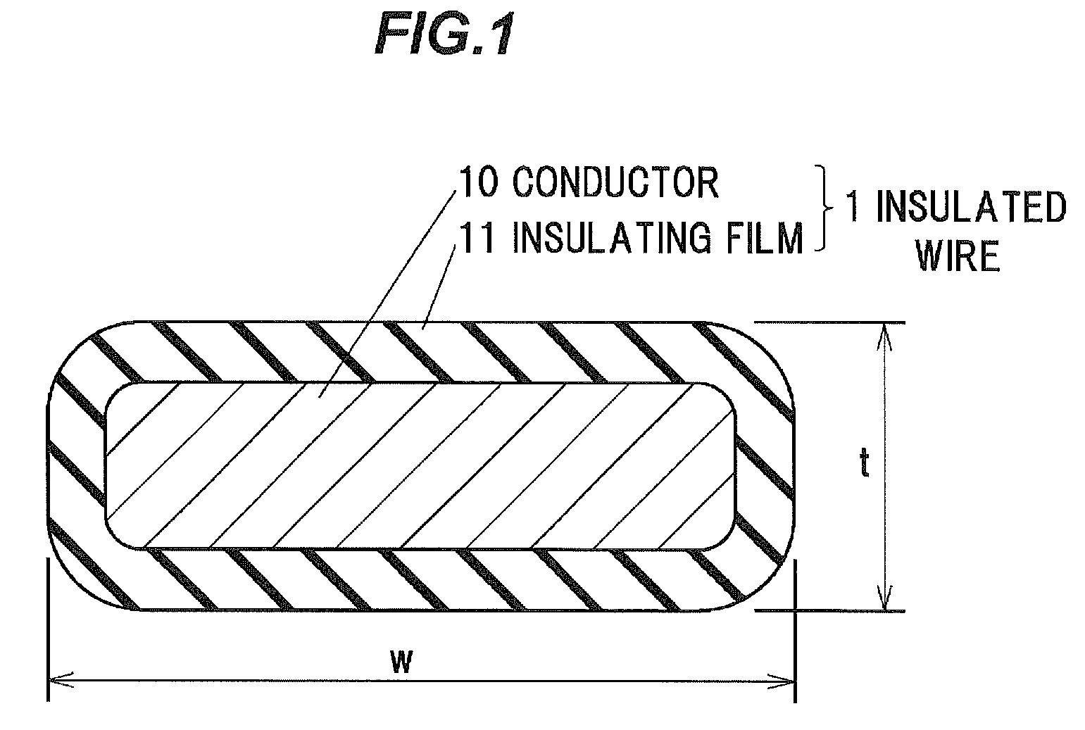
[0024]Insulated Wire

[0025]FIG. 1 is a cross-sectional view schematically showing an insulated wire 1 according to the embodiment of the invention. The insulated wire 1 is a flat type insulated wire that includes a conductor 10 and an insulating film 11 formed on the periphery of the conductor 10. Reference marks of “w” and “t” in FIG. 1 represent a width and a thickness of the insulated wire 1 respectively.

[0026]In the insulated wire 1, damage such as crack does not occur in the insulating film 11, even if a bending process is applied to the insulated wire 1, in which such a processing stress as to deform the insulating film 11 is added. For example, damage such as crack does not occur in the insulating film 11, even if the insulated wire 1 is bent by 180 degrees in the width (w) direction of the conductor 10.

[0027]The conductor 10 is a flat type conductor wire comprised of a conductive material such as copper. As the copper, oxygen free copper, low oxygen copper or the like is most...

example 1

[0059]The first insulating layer was formed by coating a flat type copper conductor with the resin varnish 1 and baking the resin varnish 1, and then the second insulating layer was formed by further coating with the resin varnish 1 and baking the resin varnish 1, so that an insulated wire of Example 1 was formed. In Example 1, the second insulating layer is formed of the resin varnish 1, thus the second insulating layer has breaking elongation percentage of 145% and glass-transition temperature of 307 degrees C.

example 2

[0060]The first insulating layer was formed by coating a flat type copper conductor with the resin varnish A and baking the resin varnish A, and then the second insulating layer was formed by further coating with the resin varnish 1 and baking the resin varnish 1, so that an insulated wire of Example 2 was formed. In Example 2, the second insulating layer is formed of the resin varnish 1, thus the second insulating layer has breaking elongation percentage of 145% and glass-transition temperature of 307 degrees C.


PUM

PropertyMeasurementUnit
breaking elongation percentageaaaaaaaaaa
molar ratioaaaaaaaaaa
sizeaaaaaaaaaa

Abstract

An insulated wire includes a flat type conductor, and an insulating film on an outer periphery of the flat type conductor. The insulating film includes a polyimide layer including a polyimide and having a breaking elongation percentage of more than 80%.

Description

[0001]The present application is based on Japanese patent application No. 2012-055675 filed on Mar. 13, 2012, the entire contents of which are incorporated herein by reference.BACKGROUND OF THE INVENTION[0002]1. Field of the Invention[0003]This invention relates to an insulated wire and, in particular, to an insulated wire configured such that an insulating film having a breaking elongation percentage of more than 80% is formed on a periphery of a flat type conductor, and a coil formed by using the insulated wire.[0004]2. Description of the Related Art[0005]In recent years, according to the increase in awareness of global environment conservation, it is expected that motor, transformer and the like are small-sized and highly-efficient. For example, with regard to motor, it is often the case that a high-power motor is mounted in an extremely small space.[0006]In case of mounting a high-power motor in an extremely small space, an insulated wire having a cross-sectional shape that is a...

Claims


Application Information

Patent Timeline
Patent Type & Authority Applications(United States)
IPC IPC(8): H01B3/30
CPCH01B3/306
Inventor HONDA, YUKIUSHIWATA, TAKAMINABESHIMA, SHUTAKIKUCHI, HIDEYUKI
Owner HITACHI METALS LTD
Why Eureka
Try Eureka