Transponder and related network node for an optical transmission network

a technology of optical transmission network and transponder, applied in the field of telecommunications, can solve the problem of limiting power consumption, and achieve the effect of reducing e/o conversion and signal processing, and reducing power consumption

Active Publication Date: 2013-09-19
ALCATEL LUCENT SAS
View PDF4 Cites 11 Cited by
  • Summary
  • Abstract
  • Description
  • Claims
  • Application Information

AI Technical Summary

Benefits of technology

[0004]With the ever increasing amount of traffic and transmission rates, which requires high-speed electronic signal processing that in a first approximation follows Moore's law, power consumption becomes a limiting factor. It is hence an object of the present invention, to provide network equipment for optical transmission networks which can operate at a reduced power consumption. This is achieved according to an aspect of the invention by reducing E / O conversion and signal processing in optical networks when not needed. The present invention hence provides a network node and a transponder for such a network node, which flexibly allows to enable or disable O / E / O conversion and / or signal processing for individual optical signals as needed.

Problems solved by technology

With the ever increasing amount of traffic and transmission rates, which requires high-speed electronic signal processing that in a first approximation follows Moore's law, power consumption becomes a limiting factor.

Method used


Image

  • Transponder and related network node for an optical transmission network
  • Transponder and related network node for an optical transmission network
  • Transponder and related network node for an optical transmission network

Examples


Embodiment Construction

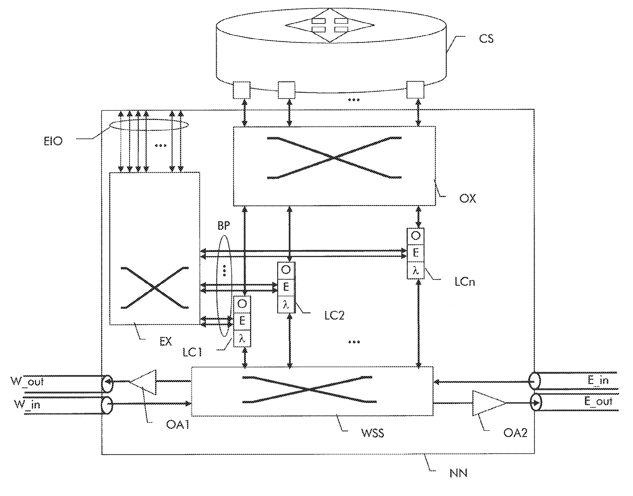
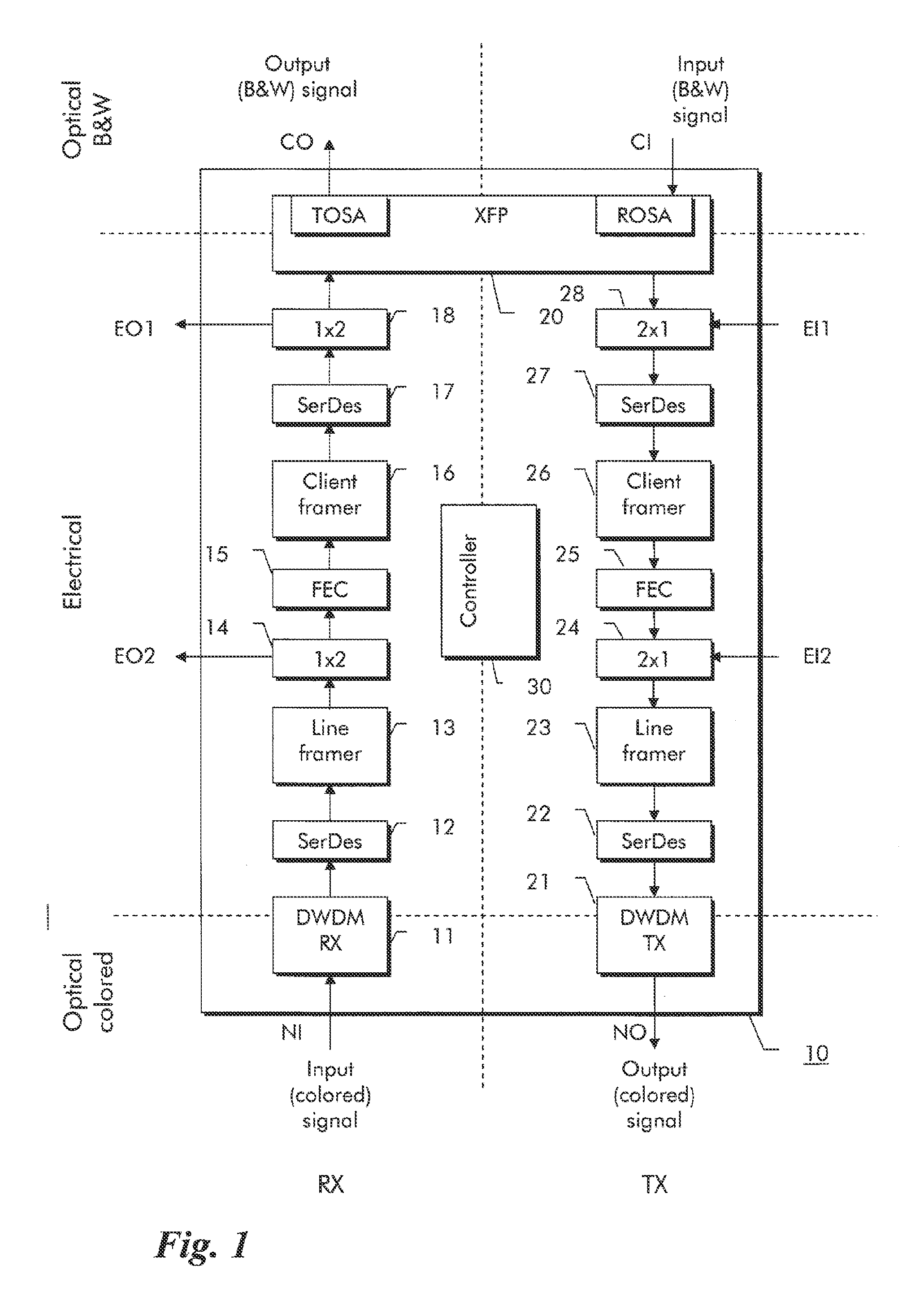
[0015]A transponder 10 for an optical network node is shown in FIG. 1. An optical transponder is a piece of equipment that receives an optical signal, then processes and re-transmits it on a new wavelength, which can be different from the received wavelength. The transponder can be used for example as part of a line card in an optical network node.

[0016]The transponder or line card 10 in FIG. 1 operates bidirectionally, i.e. receives and transmits signals in both directions. At the bottom of FIG. 1 are network side input and output ports NI, NO and at the top are customer side input and output ports CI, CO. With regard to its network side functionality, the two independent transponder directions are referred to as receiver portion RX and transmitter portion TX. In particular, the receiver portion RX of transponder 10 shown at the left-hand side of FIG. 1 contains a DWDM (dense wavelength division multiplex) optical receiver circuit 11, which receives a single DWDM wavelength channel...


PUM


Abstract

In order to reduce power consumption in network equipment for optical transmission networks, it is proposed by reducing E/O conversion and signal processing in optical networks when not needed. A network node has two or more line cards. Each line card contains a receive side transponder section with a network side optical receiver, a first electrical section, and a client side optical transmitter and a transmit side transponder section with a network side optical transmitter, a second electrical section, and a client side optical receiver. The first electrical section has at least one intermediate electrical output the second electrical section has at least one intermediate electrical input. The intermediate electrical outputs and inputs lead to an electrical switch matrix, which controllably interconnects the intermediate electrical outputs and inputs. Preferably, the transponders can additionally contain second intermediate electrical outputs and inputs additionally bypassing a Forward-Error-Correction processing function in the line cards

Description

FIELD OF THE INVENTION[0001]The present invention relates to the field of telecommunications and more particularly to a transponder and related network node for an optical transmission network.BACKGROUND OF THE INVENTION[0002]In telecommunications, high speed core networks mainly rely on optical transmission. Data signals can be modulated onto optical carriers at different wavelengths and transmitted together using wavelength division multiplexing over a same fiber span. In long-haul optical transmission, optical regenerators are provided along an optical transmission line to regenerate optical signals and remove distortions. Moreover, Forward Error Correction (FEC) processing can be applied to increase the maximum transmission distance per span and the receiver sensitivity.[0003]With the introduction of wavelength selective switches (WSS) and reconfigurable optical add / drop multiplexers (ROADMs), optical transmission networks evolve from classical point-to-point transmission more a...

Claims


Application Information

Patent Timeline
Patent Type & Authority Applications(United States)
IPC IPC(8): H04J14/02H04B10/29
CPCH04B10/29H04J14/0221H04J14/0212H04J14/02H04Q2011/0039
Inventor POINTURIER, YVANDORIZE, CHRISTIANMOREA, ANNALISA
Owner ALCATEL LUCENT SAS
Why Eureka
Try Eureka