Mold stack for a preform

a preform and stack technology, applied in the direction of coatings, etc., can solve the problem that the neck region cannot be easily formed by using the cavity and core halves

Inactive Publication Date: 2013-09-19
HUSKY INJECTION MOLDING SYST LTD
View PDF4 Cites 17 Cited by
  • Summary
  • Abstract
  • Description
  • Claims
  • Application Information

AI Technical Summary

Problems solved by technology

As is appreciated in the art, the neck region can not

Method used


Image

  • Mold stack for a preform
  • Mold stack for a preform
  • Mold stack for a preform

Examples


Embodiment Construction

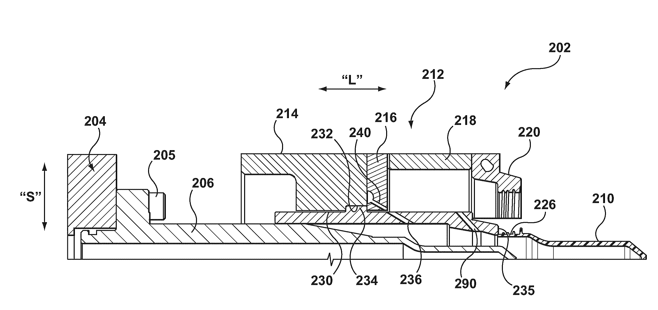
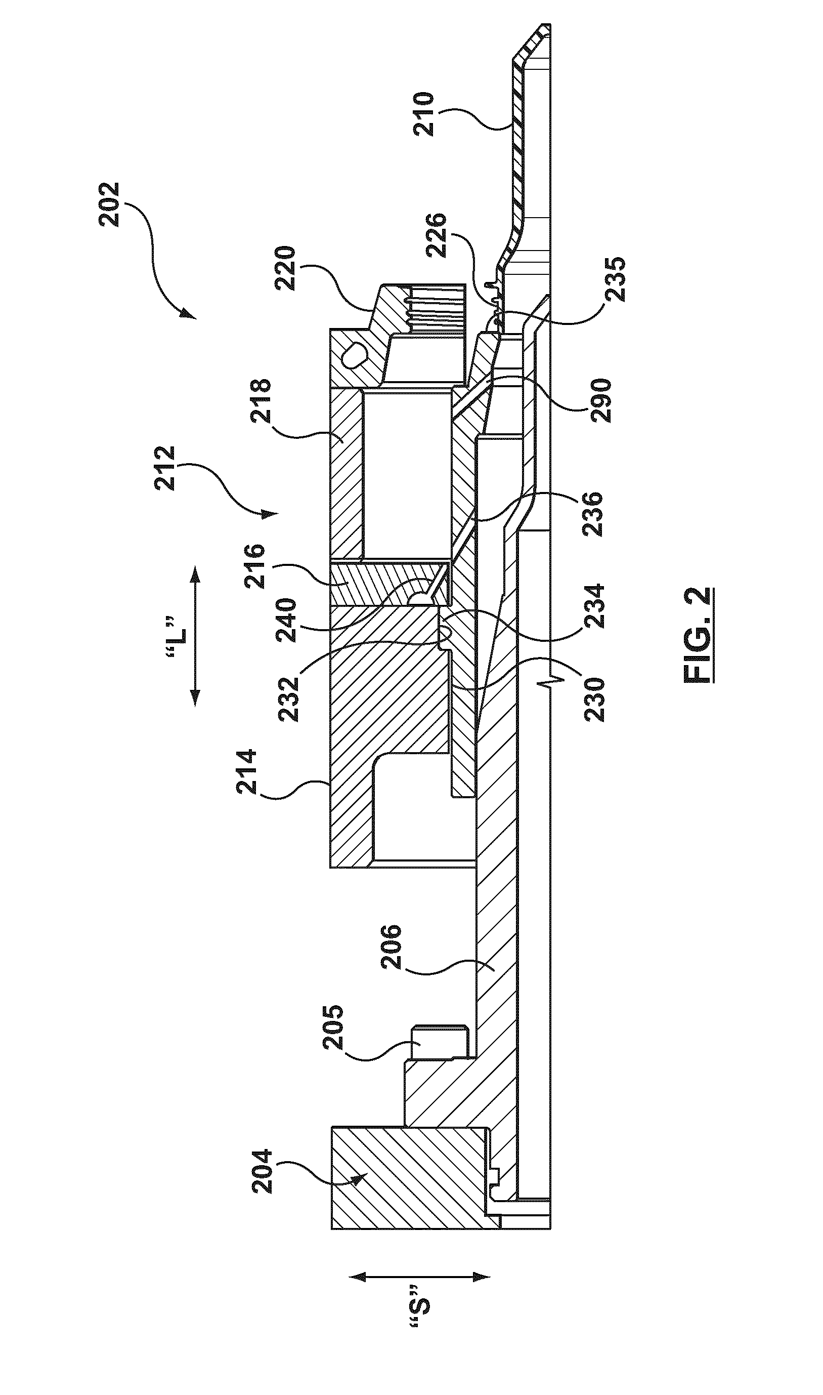
[0018]With reference to FIG. 2, a non-limiting embodiment of a portion of a mold stack 202 will now be described in greater detail, in which FIG. 2 depicts a cross section taken along a longitudinal axis thereof.

[0019]The portion of the mold stack 202, as depicted in FIG. 2, is receivable in use within a core plate 204, which is implemented according to conventional designs and, as such, will not be described in great detail herein. Suffice it to state that the mold stack 202 includes a core insert 206 operatively coupled to the core plate 204. Construction of the core insert 206 can be implemented in accordance with known techniques and, as such, will not be described in great detail herein. The core insert 206 is coupled to the core plate 204 by means of a bolt 205, however in alternative embodiments of the present invention other coupling means can be used to couple the core insert 206 to the core plate 204.

[0020]The function of the core insert 206 is also well-known in the art a...


PUM


Abstract

There is provided a stripper assembly (212) for use in a mold stack (202) for forming a preform (210) suitable for blow-molding into a final-shaped container. The stripper assembly (212) comprises a stripper plate (214) connectable, in use, to a stripper plate actuator; neck rings (220) configured to cooperate to define a portion a neck region (226) of the preform (210); a stripper ring (230) configured to define at least a portion of a top sealing surface of the neck region (226) of the preform (210); the stripper plate (214) being configured to actuate the neck rings (220) and the stripper ring (230), in unison, along substantially the whole length of a complete ejection path, which is substantially parallel to a longitudinal axis of the mold stack (202); and where-in the neck rings (220) are configured for movement in a direction substantially perpendicular to the longitudinal axis of the mold stack, over at a portion of the complete ejection path, the stripper ring (230) having an air channel (236) configured to directed a flow of fluid towards the preform.

Description

FIELD OF THE INVENTION[0001]The present invention generally relates to, but is not limited to, a molding system, and more specifically the present invention relates to, but is not limited to, a mold stack for a preform.BACKGROUND OF THE INVENTION[0002]Molding is a process by virtue of which a molded article can be formed from molding material by using a molding system. Various molded articles can be formed by using the molding process, such as an injection molding process. One example of a molded article that can be formed, for example, from polyethylene terephthalate (PET) material is a preform that is capable of being subsequently blown into a beverage container, such as, a bottle and the like.[0003]As an illustration, injection molding of PET material involves heating the PET material (or other suitable molding material for that matter) to a homogeneous molten state and injecting, under pressure, the so-melted PET material into a molding cavity defined, at least in part, by a fem...

Claims


Application Information

Patent Timeline
IPC IPC(8): B29C49/02
CPCB29B11/08B29K2105/253B29B2911/1402B29B2911/14026B29B2911/14033B29B2911/1404B29B2911/14106B29B2911/14133B29B2911/14326B29B2911/14333B29B2911/1444B29B2911/14486B29C45/43B29C49/02B29C2045/4078B29B11/14B29C2949/3024B29C2949/26B29C2949/28B29C2949/24B29C2949/22B29C2949/3032B29C2949/073B29C2949/072B29C2949/0773B29C2949/078B29C49/071B29C2949/0715
Inventor MCCREADY, DEREK ROBERTSONPAPA, RENATO
Owner HUSKY INJECTION MOLDING SYST LTD
Why Eureka
Try Eureka