Brake force control apparatus for vehicle and brake force control method for vehicle

a technology of brake force control and control apparatus, which is applied in the direction of braking system, process and machine control, instruments, etc., can solve the problems of inability to detect, the distribution control of brake force between the front and the rear wheels is sometimes inappropriately implemented, and the failure of normal brake devices, etc., to reduce vehicle deceleration, increase the excess yaw momentum, and detect accurately

Active Publication Date: 2013-09-19
TOYOTA JIDOSHA KK
View PDF8 Cites 18 Cited by
  • Summary
  • Abstract
  • Description
  • Claims
  • Application Information

AI Technical Summary

Benefits of technology

[0010]The invention provides a brake force control apparatus and a brake force control method that accurately detect the presence of a failure in a brake device and control

Problems solved by technology

Therefore, when failure determination of a brake device is based on deceleration of vehicle or deceleration of wheels, the failed brake device is sometimes determined to be normal and the front-rear wheel distribution control of brake force is sometimes implemented inappropriately.
Conversely, a normal brake device is sometimes determined to have failed and the necessary front-rear wheel distribution control of brake force is not p

Method used


Image

  • Brake force control apparatus for vehicle and brake force control method for vehicle
  • Brake force control apparatus for vehicle and brake force control method for vehicle
  • Brake force control apparatus for vehicle and brake force control method for vehicle

Examples


first embodiment

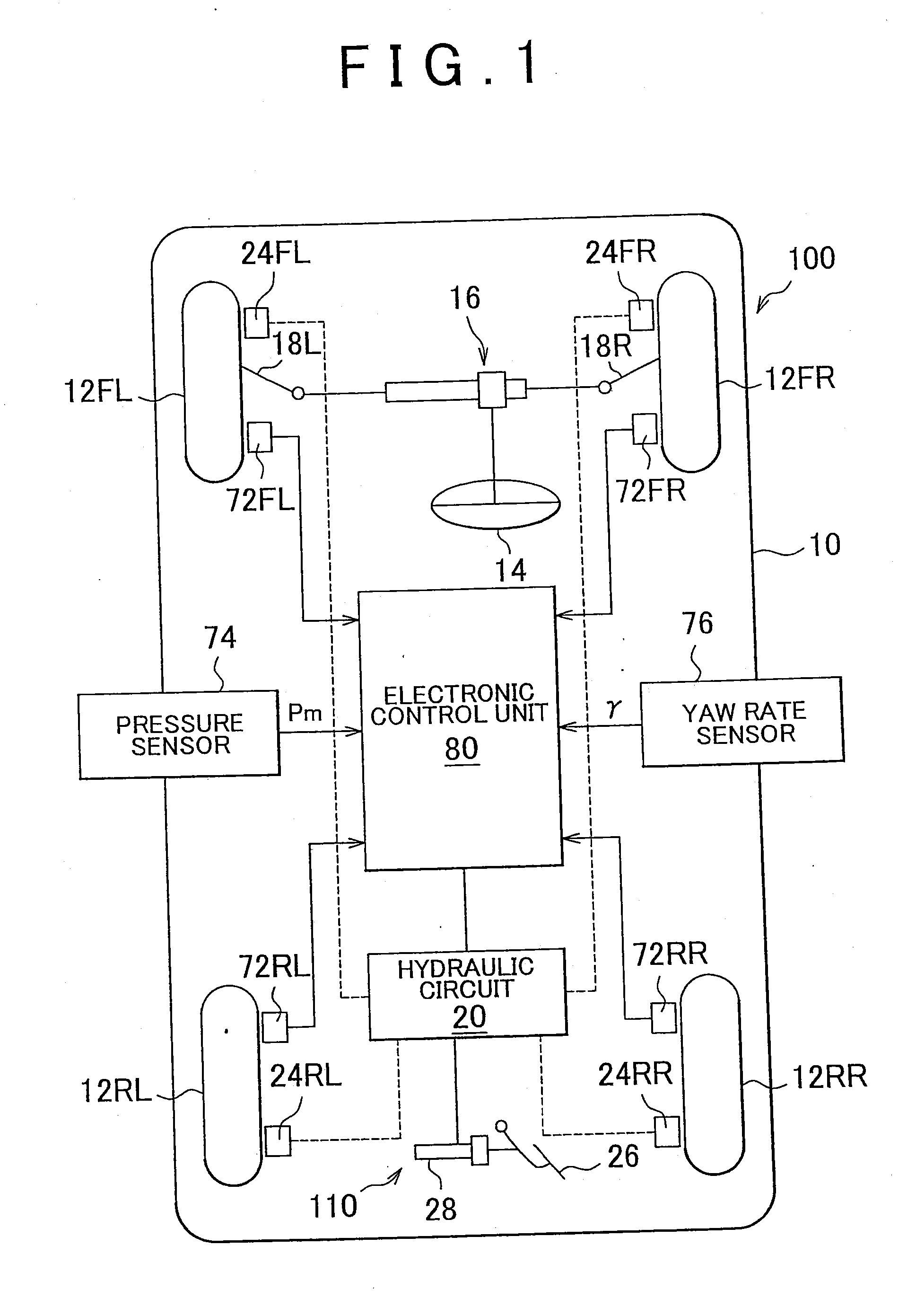
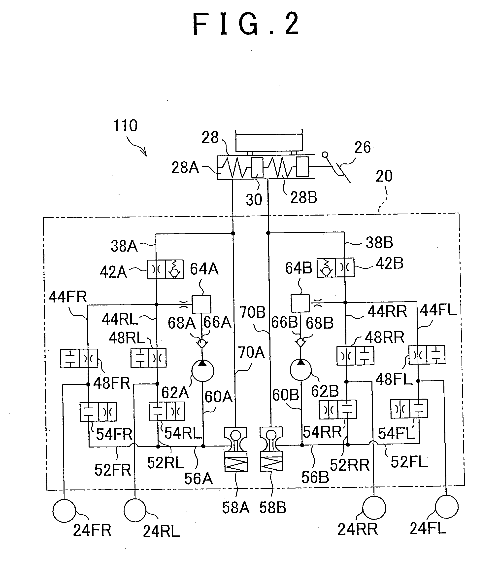
[0075]FIG. 1 is a schematic configuration diagram illustrating the first embodiment of the brake force control apparatus for a vehicle in accordance with an aspect of the invention. FIG. 2 illustrates the brake device shown in FIG. 1.

[0076]In FIG. 1, the reference numeral 100 stands for the entire brake force control apparatus of a vehicle 10. The vehicle 10 has left and right front wheels 12FL and 12FR and left and right rear wheels 12RL and 12RR. The left and right front wheels 12FL and 12FR that are the steered wheels are steered via tie rods 18L and 18R by a power steering device 16 of a rack and pinion type that is driven in response to the operation of a steering wheel 14 performed by the driver.

[0077]The brake force of each wheel is controlled by controlling a pressure Pi (i=fr, fl, rr, rl) inside wheel cylinders 24FR, 24FL, 24RR, 24RL, that is, the brake pressure of each wheel, by a hydraulic circuit 20 serving as a brake actuator of the brake device 110. As shown in FIG. 2,...

second embodiment

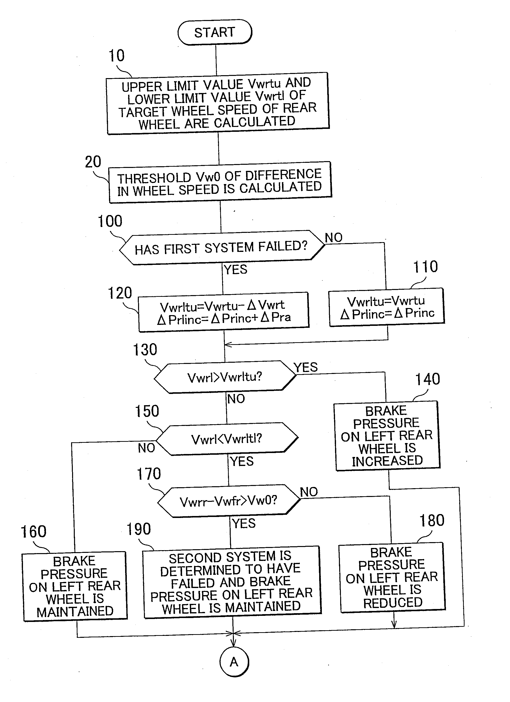
[0142]FIGS. 5 and 6 are flowcharts illustrating the front-rear wheel distribution control routine for a brake force in the second embodiment of the brake force control apparatus for a vehicle in accordance with the invention. In FIGS. 5 and 6, the steps identical to those shown in FIGS. 3 and 4 are assigned with step numbers identical to the step numbers assigned in FIGS. 3 and 4. The same relates to other below-described embodiments.

[0143]In the second embodiment, where step 10 is completed, step 30 is implemented instead of step 20.

[0144]In step 30, it is determined whether the sign of the difference Vwrl−Vwfl in wheel speed between the left front and rear wheels is different from the sign of the difference Vwrr−Vwfr in wheel speed between the right front and rear wheels, that is, whether or not the first or second system has failed. Where a positive determination is made, the control advances to step 70, and where a negative determination is made, the control advances to step 65....

third embodiment

[0161]FIG. 7 is a flowchart illustrating the first half of the front-rear wheel distribution control routine for a brake force in the third embodiment of the brake force control apparatus for a vehicle in accordance with the invention.

[0162]In the third embodiment, once step 10 is completed, step 21 is implemented, and once step 21 is completed, the control advances to step 40.

[0163]In step 21, a threshold Vwf0 for the difference in wheel speed between the left and right front wheels and a threshold Vwr0 for the difference in wheel speed between the left and right rear wheels that serve for failure determination are calculated on the basis of vehicle speed V, vehicle deceleration Vd, and vehicle deceleration gradient Vdd. In this case, the thresholds Vwf0 and Vwr0 for the difference are calculated so as to assume higher values when the vehicle speed V, vehicle deceleration Vd, and vehicle deceleration gradient Vdd are large.

[0164]In step 40, it is determined whether or not the absol...


PUM


Abstract

A brake force control apparatus includes a diagonal two-system brake device and performs front-rear wheel distribution control of brake force by individually controlling the brake pressure of the left and right rear wheels so as to obtain a target relationship between a wheel speed of the left and right rear wheels and the front wheels during braking. It is determined whether or not a difference in wheel speed between one wheel of one system and one wheel of the other system or a difference in wheel speed between the other wheel of the one system and the other wheel of the other system exceeds a threshold. When the threshold is exceeded, the reduction of brake pressure by the front-rear wheel distribution control of brake force is not performed with respect to a rear wheel with a lower wheel speed from among the left and right rear wheels.

Description

BACKGROUND OF THE INVENTION[0001]1. Field of the Invention[0002]The invention relates to a brake force control apparatus for a vehicle that performs front-rear wheel distribution control of brake force by individually controlling the brake pressure of the left and right rear wheels so as to obtain a target relationship between the slip degree index value of the left and right rear wheels and the slip degree index value of the front wheels during braking. More particularly, the invention relates to a brake force control apparatus and a brake force control method that perform front-rear wheel distribution control of brake force in a vehicle having a brake device provided with a brake pressure control system for the left front wheel and right rear wheel and a brake pressure control system for the right front wheel and left rear wheel.[0003]2. Description of Related Art[0004]A brake force control apparatus that performs front-rear wheel distribution control of brake force is available. ...

Claims


Application Information

Patent Timeline
IPC IPC(8): B60T8/176B60T8/92B60T8/26B60T8/1761
CPCB60T7/042B60T8/1755B60T8/1766B60T8/268B60T8/4872B60T8/885B60T8/92B60T13/686B60T17/221B60T2270/403B60T8/176B60T8/1761B60T8/26B60T13/662
Inventor WATANABE, YOSHINORI
Owner TOYOTA JIDOSHA KK
Why Eureka
Try Eureka