Power Tool

a power tool and power technology, applied in the field of power tools, can solve the problems of crank shafts and integral crank axes, and achieve the effect of facilitating the renewal of saw blades

Inactive Publication Date: 2013-09-26
BLACK & DECKER INC
View PDF4 Cites 13 Cited by
  • Summary
  • Abstract
  • Description
  • Claims
  • Application Information

AI Technical Summary

Benefits of technology

[0015]Preferably, the second end of each shaft comprises a blade clamp detachably connected to a respective saw blade. The blade clamp facilitates renewal of the saw blades when damaged or worn.

Problems solved by technology

Independent driven gears, each having its own crank pin and driven gear axle, divides the crank axis and diminishes counter-rotational torque which may otherwise be transmitted along, and cause fatigue in, an integral crank axis such as a crank shaft.

Method used


Image

  • Power Tool
  • Power Tool
  • Power Tool

Examples


Embodiment Construction

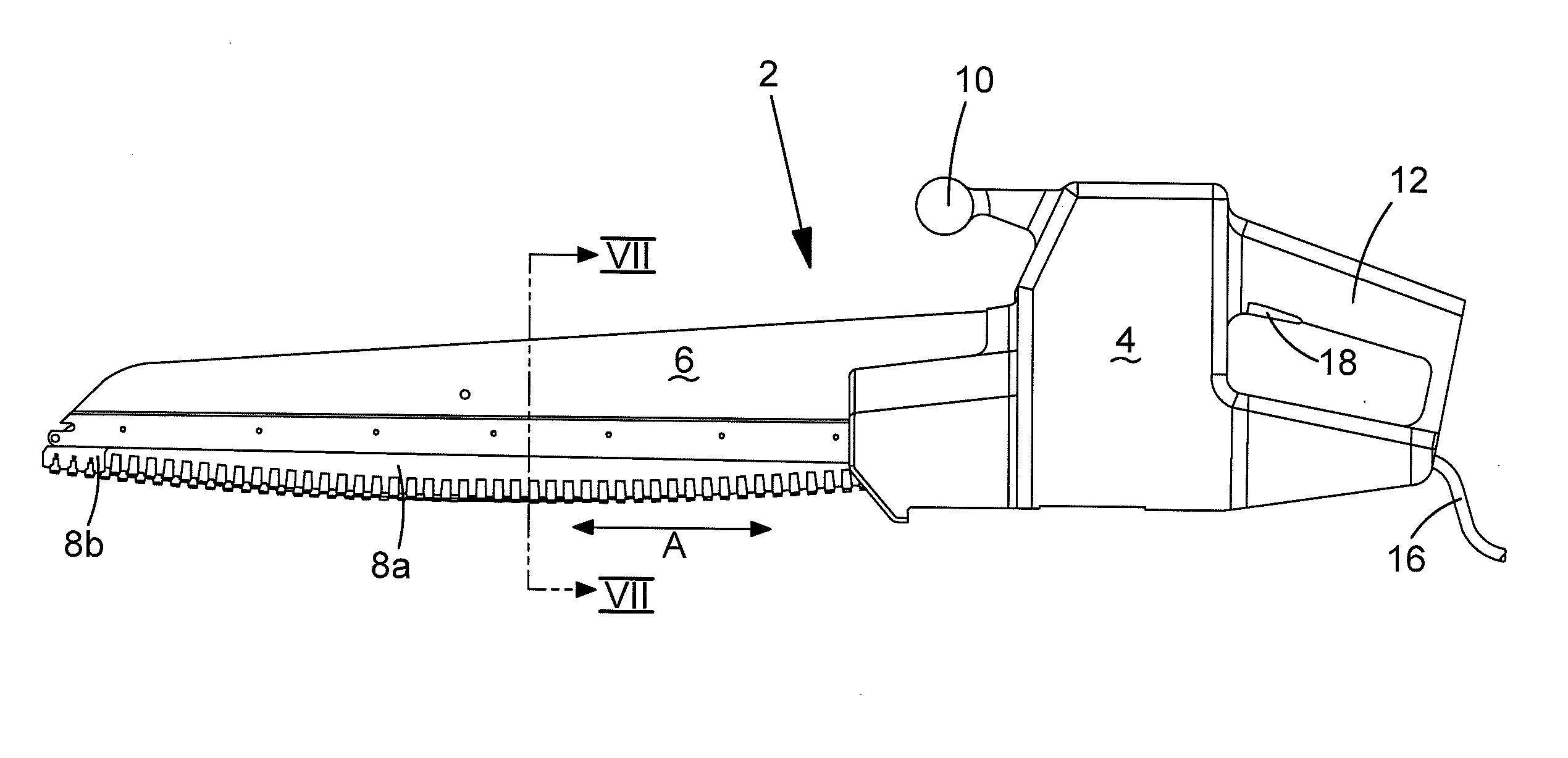
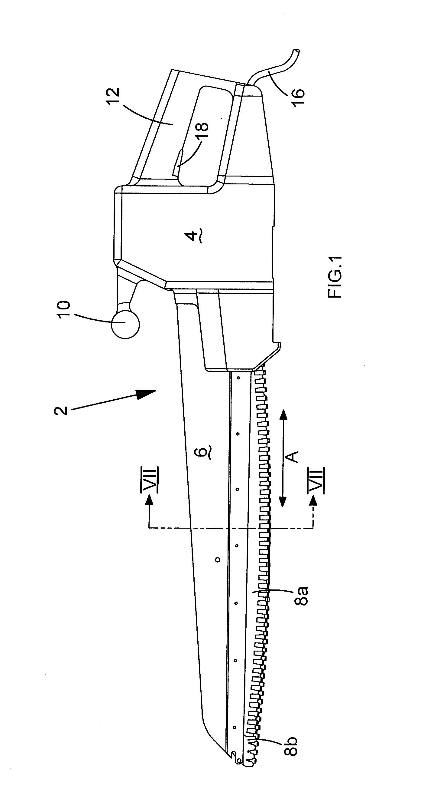
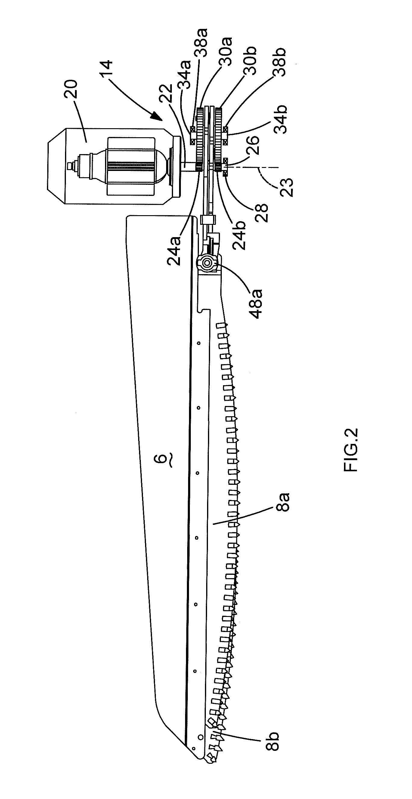
[0026]Referring to FIG. 1, a power-driven saw 2 comprises a housing 4, an elongate saw blade support 6 and a pair of saw blades 8a, 8b for counter-reciprocating rectilinear cutting motion in the direction of double-headed arrow A. The housing comprises a front handle 10 and a rear handle 12 each to be grasped by a user of the power-driven saw. The housing encloses a drive mechanism 14, a mains electrical power supply cable 16 depending from the rear of the housing, an on / off trigger switch 18 protruding from inside the rear handle and an electric motor 20 fixed to the interior of the housing. The blade support is fixed to the housing at a location below the front handle. The saw blades are supported for sliding motion under the blade support. The saw blades are coupled to the drive mechanism.

[0027]In the present embodiment, the electric motor 20 provides the power-saw 2 with a drive device, although such a power tool may alternatively have a combustion engine or an electric motor po...


PUM

PropertyMeasurementUnit
flexibleaaaaaaaaaa
lengthaaaaaaaaaa
widthaaaaaaaaaa

Abstract

A power-driven saw comprising a housing; a blade support; a motor coupled to a drive shaft; a pair of saw blades slideably supported by the blade support; and a drive mechanism for generating reciprocating rectilinear motion of the saw blades in response to rotation of the drive shaft. The drive mechanism comprises a crank assembly with a pair of diametrically-opposed crank pins rotatable about a crank axis in response to rotation of the drive shaft; and a pair of connecting-rods. The drive shaft extends from the motor, between rotational sweep of the crank pins and reciprocating sweep of the drive couplings and to where a bearing fixed in relation to the motor supports the drive shaft for rotation. The connecting rods are shaped to avoid contact with the drive shaft during rotation thereof.

Description

CROSS-REFERENCE TO RELATED APPLICATIONS[0001]The present application claims priority to British Patent Application Number 1205272.6, filed Mar. 26, 2012, which is incorporated herein by reference in its entirety.FIELD OF THE INVENTION[0002]The present invention relates to a portable power-driven saw of the type using reciprocating rectilinear motion to perform cutting operations.BACKGROUND OF THE INVENTION[0003]A portable power-driven saw is disclosed by U.S. patent publication No. 4,031,622. The power-driven saw comprises a blade support; a motor coupled to a drive shaft rotatable by the motor; a saw blade slideably supported by the blade support for reciprocating rectilinear motion; and a drive mechanism for generating reciprocating rectilinear motion of the saw blade in response to rotation of the drive shaft. The drive mechanism operates like a crank shaft. A link member connects a rotating crank pin to the saw blade. The link member has a pair of arms defining an aperture throu...

Claims


Application Information

Patent Timeline
Patent Type & Authority Applications(United States)
IPC IPC(8): B23D49/00
CPCB23D49/003B23D51/16B23D49/006
Inventor ARMSTRONG, JONATHAN
Owner BLACK & DECKER INC
Why Eureka
Try Eureka