Self-reinforced masonry blocks, walls made from self-reinforced masonry blocks, and method for making self-reinforced masonry blocks

a self-reinforced masonry and wall technology, applied in the field of self-reinforced masonry blocks, can solve the problems of difficulty in achieving sufficient ductility and energy dissipation, limited ductility, and often inconvenient construction of reinforced concrete blocks

Active Publication Date: 2013-09-26
MCMASTER UNIV
View PDF46 Cites 6 Cited by
  • Summary
  • Abstract
  • Description
  • Claims
  • Application Information

AI Technical Summary

Benefits of technology

[0019]In one aspect, the present invention is directed to a self-reinforced masonry block. The self-reinforced masonry block comprises a main body having opposed substantially parallel stacking surfaces and having at least one tubular cell defined therethrough from one of the stacking surfaces to the other stacking surface. Each cell has a longitudinal axis and a longitudinal length defined by the stacking surfaces. At least one hollow confining reinforcement is embedded in the main body, with each confining reinforcement surrounding a corresponding cell along the longitudinal length thereof Each confining reinforcement extends substantially entirely along the longitudinal length of its corresponding cell and terminates inwardly of the stacking surfaces.

Problems solved by technology

However, the extent of ductility is limited by compression failure of the concrete block at relatively low compression strain.
However, it is very challenging to achieve sufficient ductility and energy dissipation prior to compression failure of the concrete block.
Hence, reinforced concrete block construction is often not economically competitive and sometimes not technically feasible.
Changes in recent building codes have imposed limitations affecting reinforced masonry construction with the result that use of this most common building material has been significantly limited.
Where a structure has been appropriately designed to accept damage but prevent collapse, in conditions beyond the ultimate limit state but within the design limit, the structure may be visibly damaged but will retain most (at least 80%) of its original strength and, in the case of earthquakes, the additional accepted damage produces increased ductility and energy dissipation.
In standard hollow block construction, compression failure occurs at stresses well below the compressive strength of individual blocks as a result of incompatibility between the mortar and the block material.
Under vertical compression, the larger lateral expansion of the softer mortar creates lateral tension in the blocks which results in development of vertical cracks through the webs and face shells of the block, leading to sudden crushing of the combined material at relatively low levels of vertical strain.
However, when grout is used to fill the cells created in the hollow concrete block construction, addition of this third material creates a more complex condition where the different stress-strain properties of the grout, the discontinuities in the column of grout created by imperfect alignment of the block cells from course to course, wedging action due to the tapered shape of face shells and webs, and shrinkage of the grout, all combine to produce a lower material strength than attained in the ungrouted assemblage.
Although changes in geometry of the cells in the hollow masonry block and use of shrinkage compensating grout can reduce the decrease in observed strength, these approaches are not fully effective and have undesirable economic impact.
This brittle property of grouted masonry and of concrete products in general has been understood for some time as a limiting factor in use of concrete block construction, particularly for seismic design where economic design requires ductile behavior.
Such a large spacing limits the effectiveness of the confinement and effectiveness of support against buckling of enclosed vertical compression reinforcement.
Reducing the height of the blocks to reduce the spacing distance demands handling more blocks and laying more mortar, which can dramatically increase construction cost.
In addition, the effectiveness of such reinforcement is limited because, for a typical grouted cell occupying less than 45% of the solid volume, less than 30% of the section can be effectively confined.
Following crumbling of the block and grout outside of the spiral, the residual confined area is prone to buckling and cannot develop sufficient extra strength to compensate for the area lost after the material outside of the confined region fails in compression.
Thus, achieving increased ductility in masonry block construction using techniques mentioned above involves practical difficulties and may also involve significantly increased labour costs.

Method used


Image

  • Self-reinforced masonry blocks, walls made from self-reinforced masonry blocks, and method for making self-reinforced masonry blocks
  • Self-reinforced masonry blocks, walls made from self-reinforced masonry blocks, and method for making self-reinforced masonry blocks
  • Self-reinforced masonry blocks, walls made from self-reinforced masonry blocks, and method for making self-reinforced masonry blocks

Examples


Embodiment Construction

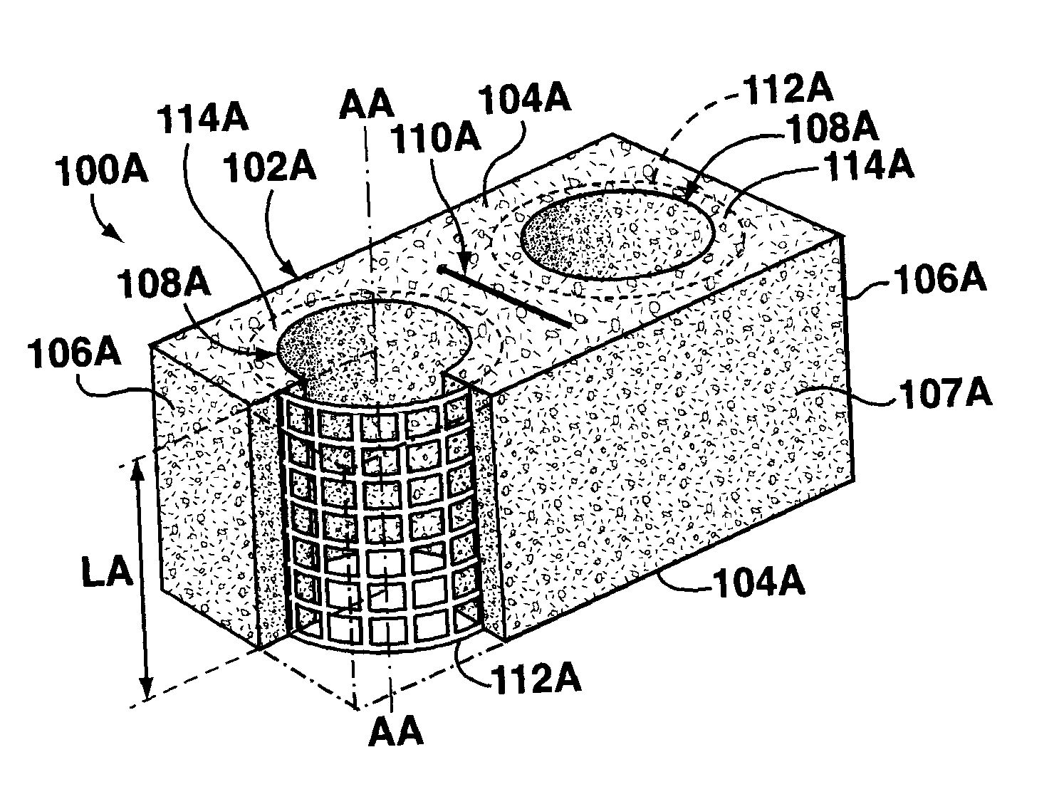
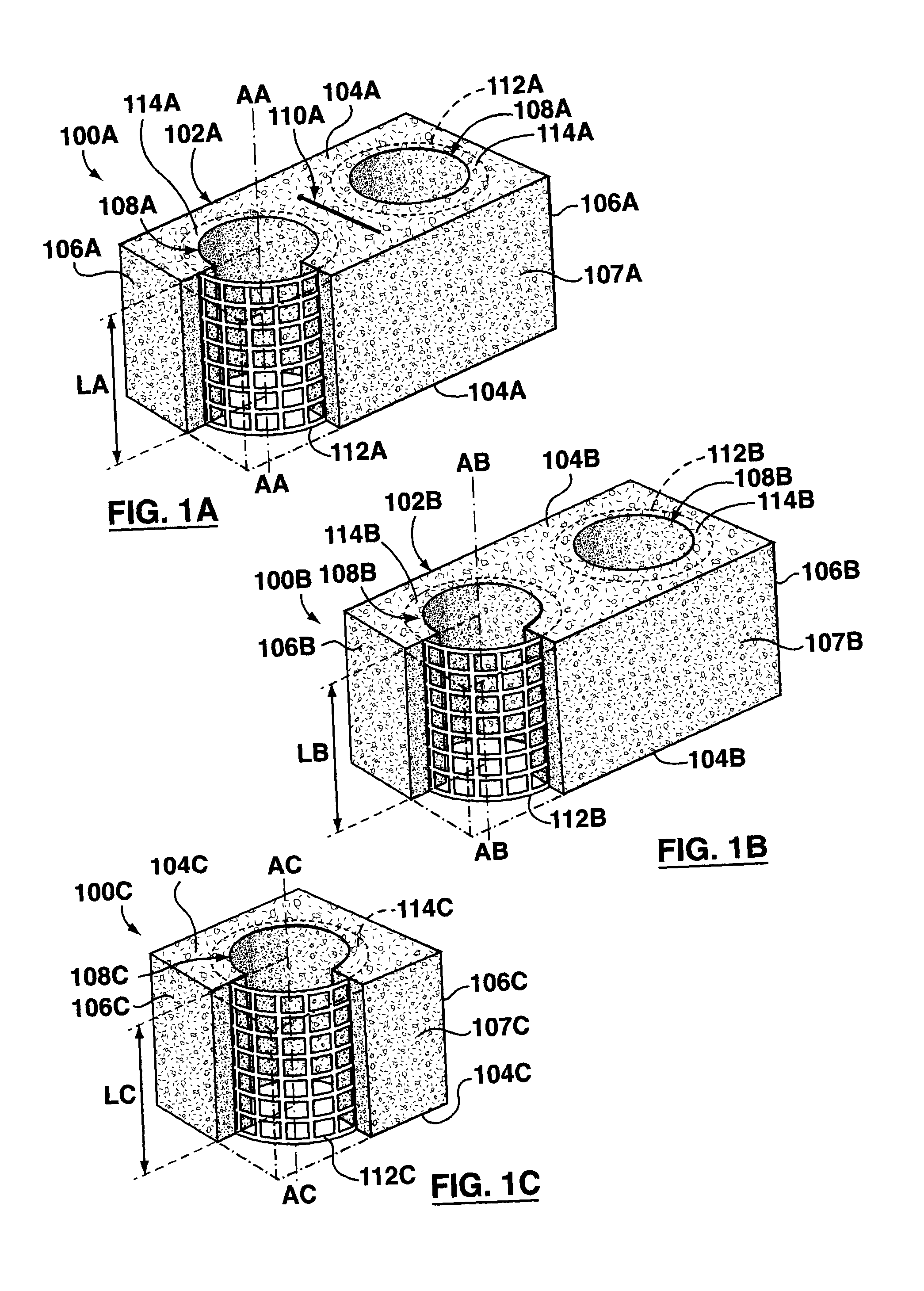
[0045]Reference is now made to FIG. 1A, which shows an exemplary self-reinforced masonry block 100A according to an aspect of the present invention. The masonry block 100A comprises a main body 102A having opposed substantially parallel stacking surfaces 104A. The main body 102A of the illustrated masonry block 102A is formed from concrete. In the illustrated embodiment the main body 102A is parallepipedic, and hence also has flat ends 106A that are architecturally suitable for use at the ends of walls, where the highest compressive stresses occur in shear walls during a seismic event, and flat side walls 107A. The exemplary masonry block 100A in FIG. 1A has dimensions of 190×190×390 mm

(758×758×1558

inches) and has the same external size and shape as, and is therefore compatible with, standard conventional concrete blocks of the same dimensions. Other suitable shapes and sizes may also be used for self-reinforced masonry blocks according to aspects of the present invention. A pair of...


PUM

PropertyMeasurementUnit
diameteraaaaaaaaaa
diameteraaaaaaaaaa
Poisson's Ratioaaaaaaaaaa

Abstract

A self-reinforced masonry block comprises a main body having opposed substantially parallel stacking surfaces and at least one tubular cell defined therethrough from one stacking surface to the other. At least one confining reinforcement is embedded in the main body to surrounding a corresponding cell. Each confining reinforcement extends substantially entirely along the longitudinal length of its corresponding cell and terminates inwardly of the stacking surfaces. The self-reinforced masonry blocks may be used in construction of a grout-filled, vertically reinforced masonry block wall, with the self-reinforced masonry blocks being used for those portions of the wall where the grouted cells are prone to crushing due to high levels of compressive stress, and conventional unreinforced masonry blocks being used for other portions of the wall. A method for making the self-reinforced masonry blocks is also described.

Description

CROSS-REFERENCE TO RELATED APPLICATION[0001]This application claims priority to U.S. Provisional Application No. 61 / 382,964 filed on Sep. 15, 2010.FIELD OF INVENTION[0002]The present invention relates to masonry blocks, and more particularly to self-reinforced masonry blocks.BACKGROUND OF THE INVENTION[0003]Common masonry walls are made of hollow concrete blocks and mortar; the hollow portions of the blocks are typically referred to as “cells”. The cells reduce the weight of block that the mason must lift into place during construction, and also enable vertical reinforcement to be installed in the wall. For added resistance to lateral loads, grout and vertical reinforcements, such as steel reinforcing bars, are placed in the cells of the block. Filling of the block cells also enhances the compression strength of concrete block walls under vertical loads. Placing vertical steel reinforcing bars in the block cells enhances the flexural strength of the wall to improve ductility through...

Claims


Application Information

Patent Timeline
Patent Type & Authority Applications(United States)
IPC IPC(8): E04B2/26B28B1/08
CPCB28B7/183B28B1/08E04B2/26B28B23/02B28B1/087E04B2/02E04B2/24E04B2002/0256E04C1/39
Inventor TOOPCHINEZHAD, HAMIDDRYSDALE, ROBERTTAIT, MICHAEL
Owner MCMASTER UNIV
Why Eureka
Try Eureka