

Methods of forming structures for downhole applications, and related downhole structures and assemblies
a technology of forming structures and downhole applications, applied in the directions of transportation and packaging, synthetic resin layered products, paper/cardboard containers, etc., can solve the problems of limiting operational efficiency, degrading the interfacial materials of structures, tools and assemblies used in various downhole applications, and exhibiting extremely aggressive environments, etc., to achieve enhanced mechanical strength, thermal resistance, chemical resistance, and enhanced mechanical strength.
- Summary
- Abstract
- Description
- Claims
- Application Information
AI Technical Summary
Benefits of technology
Problems solved by technology
Method used
Image

Examples
Embodiment Construction
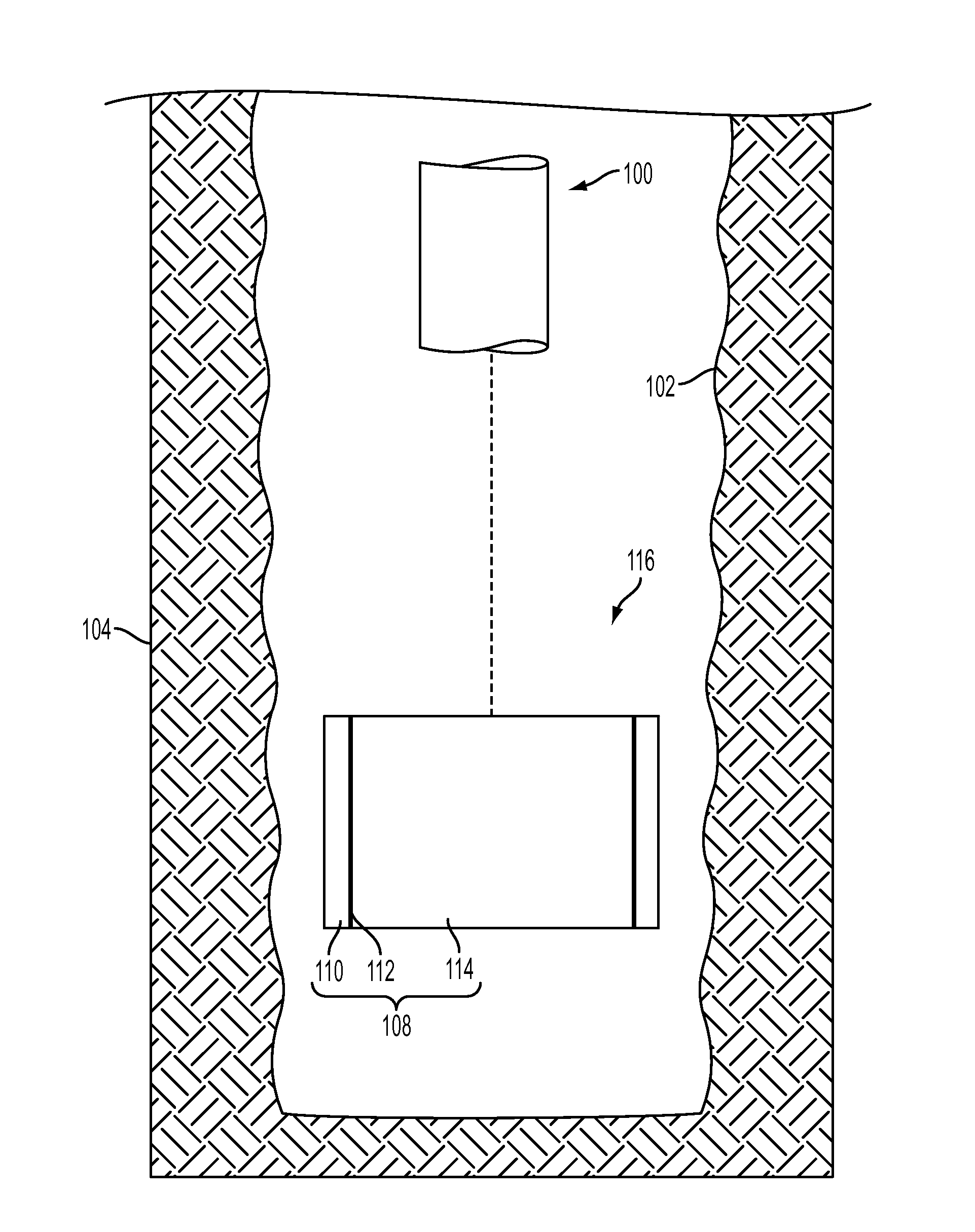
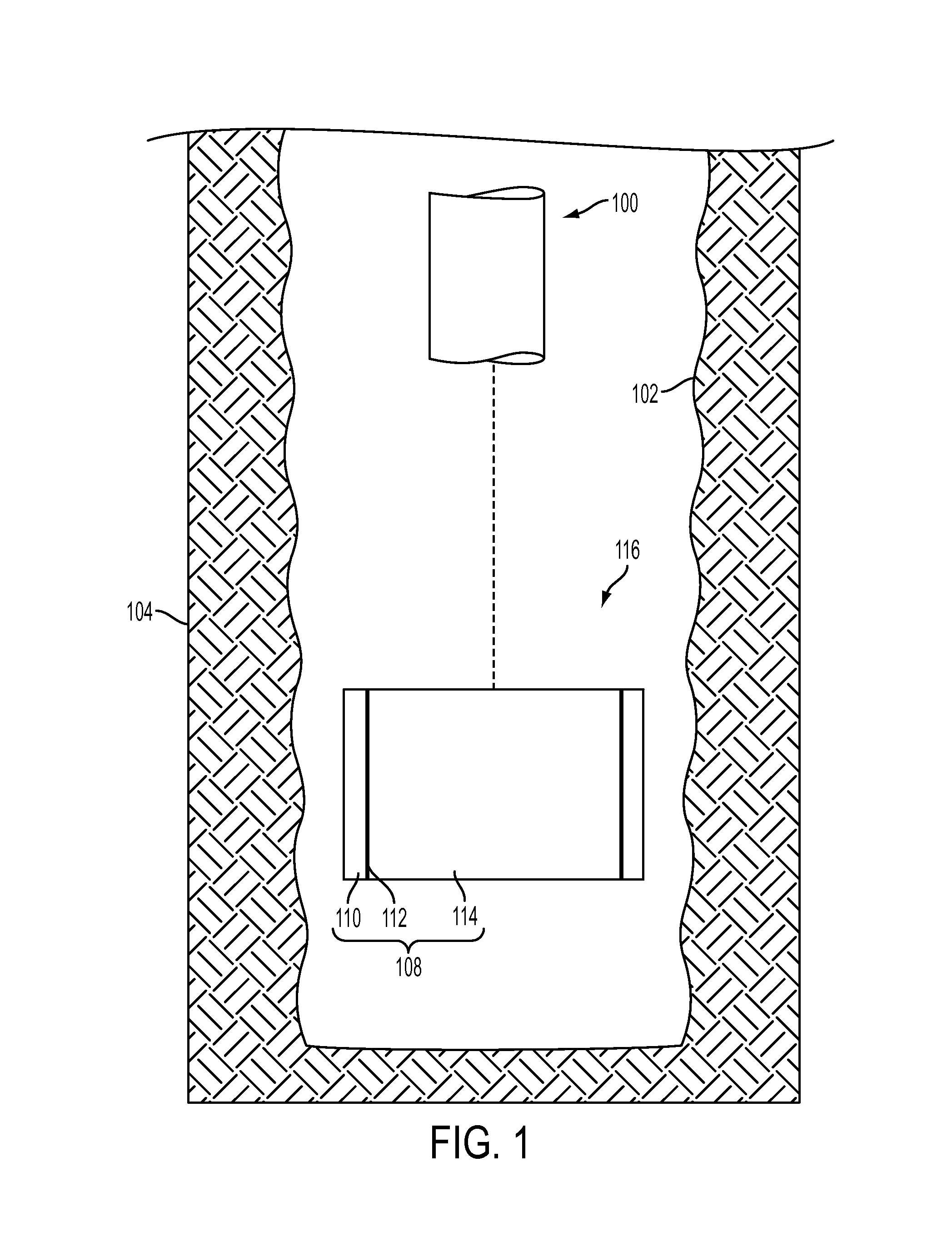
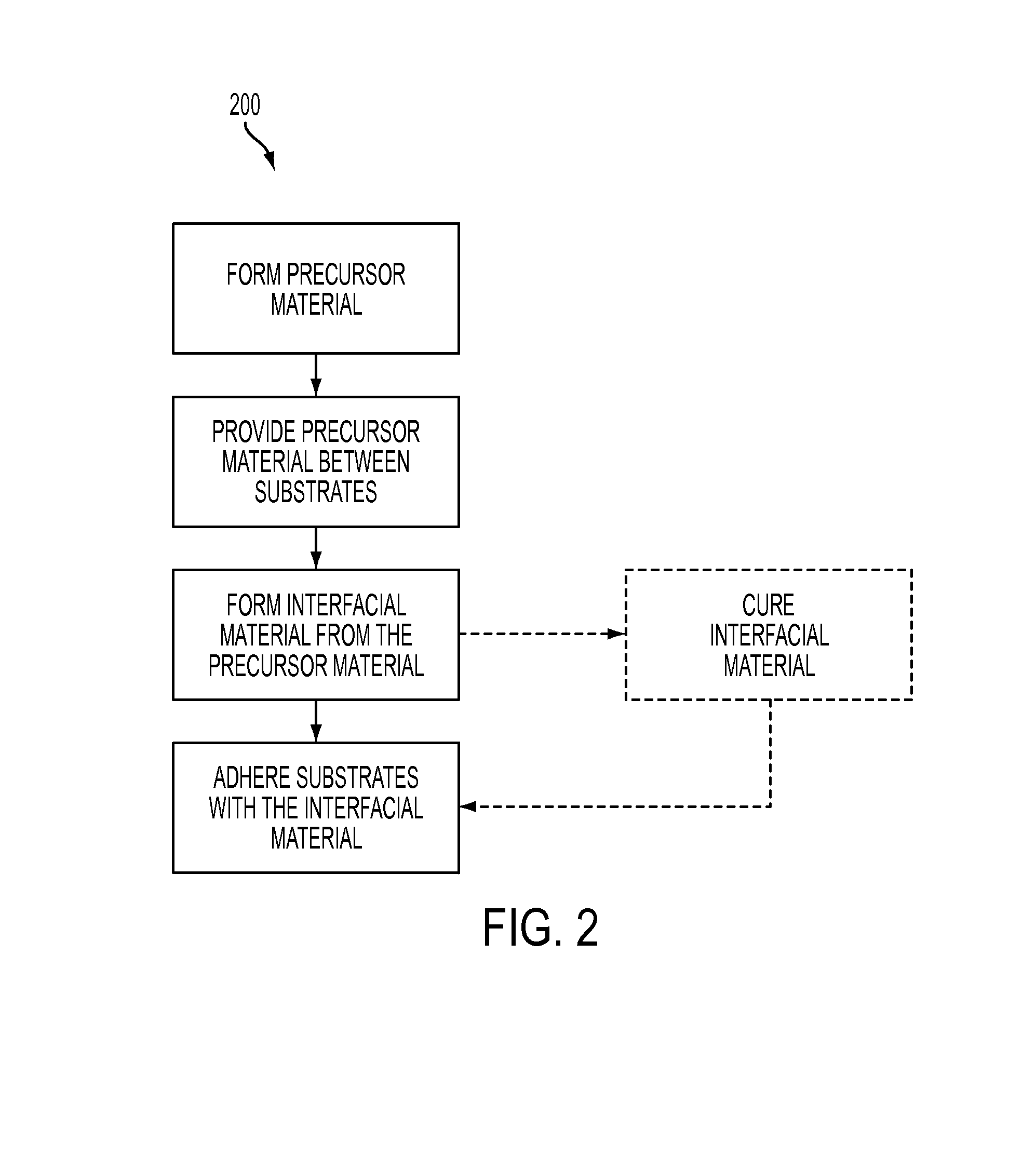
[0010]Methods of forming structures for use in downhole applications are described, as are downhole structures and downhole assemblies. In some embodiments a method of forming a structure for a downhole application comprises forming interfacial material comprising at least one of self-reinforced polyphenylene, polyphenylene sulfide, polysulfone, and polyphenylsulfone between a first substrate and a second substrate. The interfacial material and downhole structures, tools, and assemblies including the interfacial material may exhibit enhanced properties (e.g., enhanced mechanical strength, adhesion strength, wear resistance, thermal resistance, chemical resistance, etc.) favorable to the use of the interfacial material and the downhole structures, tools, and assemblies incorporating the interfacial material in downhole applications. The methods, materials, and structures of the disclosure may increase the efficiency of downhole operations and reduce costs as compared to corresponding...
PUM
| Property | Measurement | Unit |
|---|---|---|
| temperature | aaaaa | aaaaa |
| pressures | aaaaa | aaaaa |
| temperatures | aaaaa | aaaaa |
Abstract
Description
Claims
Application Information