Digital receiver and waveform compensation method

Active Publication Date: 2013-09-26
NEC CORP
View PDF6 Cites 36 Cited by
  • Summary
  • Abstract
  • Description
  • Claims
  • Application Information

AI Technical Summary

Benefits of technology

[0019]The present invention can provide a digital receiver and a wavefor

Problems solved by technology

There has been an issue in the coherent receiver not associated with the digital signal processing that stable reception is difficult due to an offset and polarization fluctuation in frequency and phase of LO (local oscillator) light.
Consequently, the

Method used


Image

  • Digital receiver and waveform compensation method
  • Digital receiver and waveform compensation method
  • Digital receiver and waveform compensation method

Examples


first exemplary embodiment

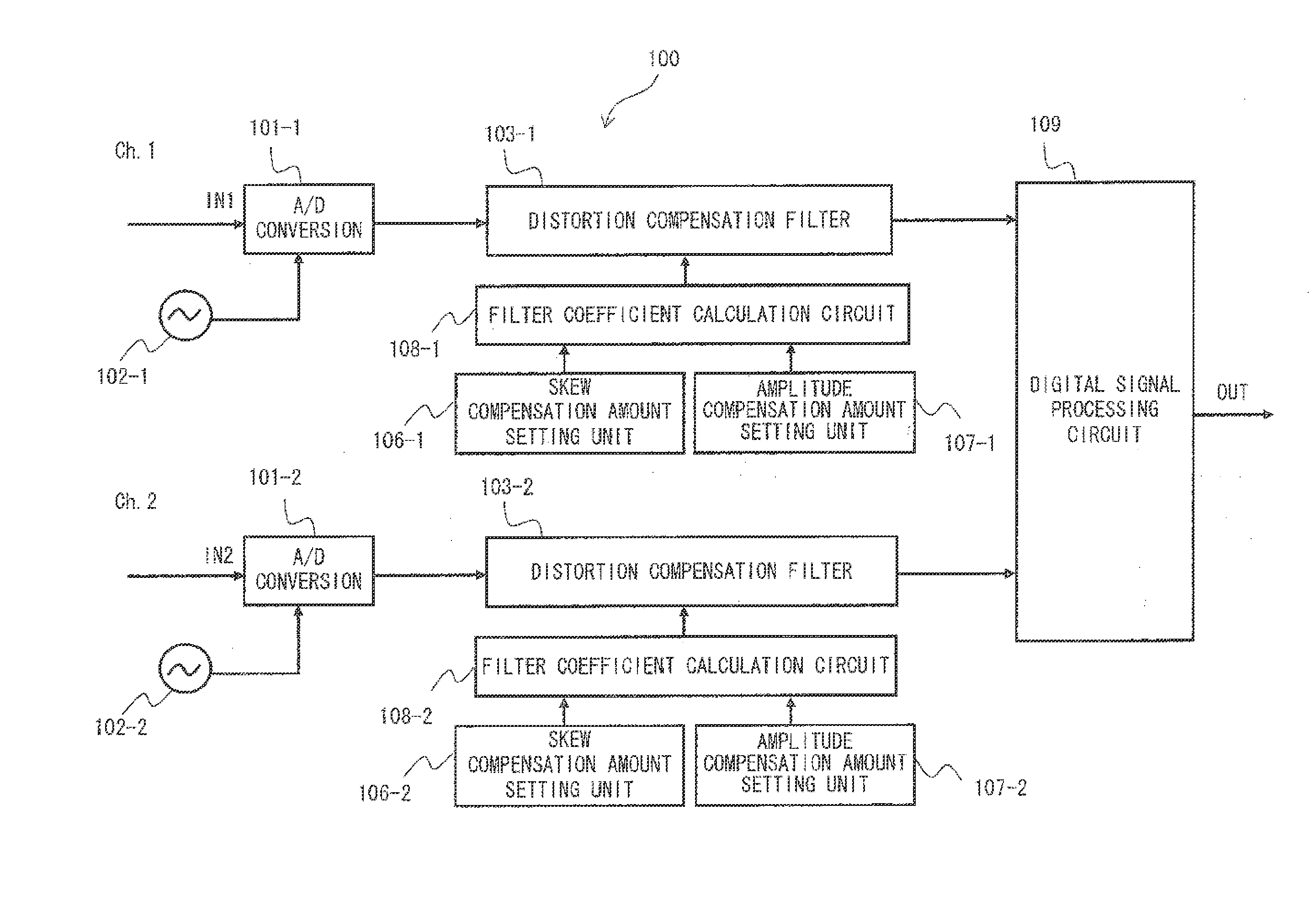
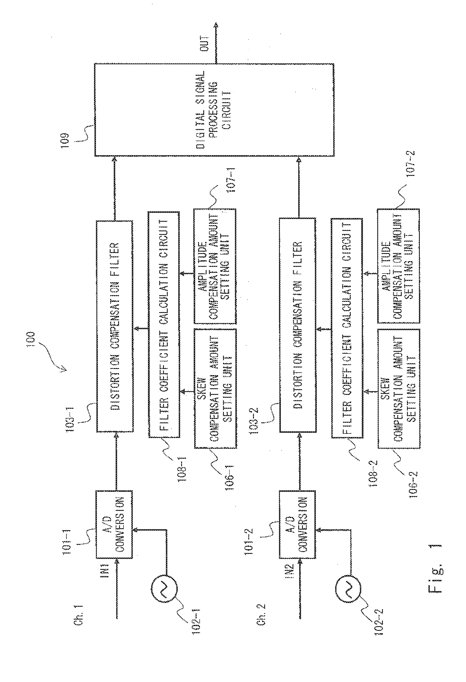
[0034]Hereinafter, exemplary embodiments of the present invention are explained with reference to the drawings. First, illustrated below is a configuration example of a digital receiver according to a first exemplary embodiment of the present invention using FIG. 1. A digital receiver 100 includes A / D converters 101, A / D converter identification clocks 102, distortion compensation filters 103, skew compensation amount setting units 106, amplitude compensation amount setting units 107, filter coefficient calculation circuits 108, and a digital signal processing circuit 109. Note that in FIG. 1, suppose that there are two channels of the units having the similar functions, and the units are denoted by −1, −2, for example, to distinguish the units. The digital receiver according to the first exemplary embodiment may include only one channel of the unit. Unless as otherwise necessary to distinguish the units, the units are described as, for example, “A / D converters 101”, and not disting...

second exemplary embodiment

[0068]Next, a second exemplary embodiment of the present invention is explained. FIG. 7 is a diagram showing a configuration example of a digital receiver 700 according to the second exemplary embodiment of the present invention. In FIG. 7, a digital receiver 700 includes a polarization diversity 90° hybrid 701, optical / electrical (0 / E) converters 702, A / D converters 703, a distortion compensation filter 704, a skew compensation amount setting unit 707, an amplitude compensation amount setting unit 708, a filter coefficient calculation unit 709, and a digital signal processing circuit 710.

[0069]In FIG. 7, when there are a plurality of units having the similar functions, the units are denoted by −1, −2, for example, to distinguish the units. Unless as otherwise necessary to distinguish the units, the “O / E converter 702-1”, the “O / E converter 702-2” and the like are described as the “O / E converter 702”.

[0070]Following is an explanation for an operation of the digital receiver 700 acco...

third exemplary embodiment

[0079]Next, a third exemplary embodiment of the present invention is explained. FIG. 9 is a diagram showing a configuration example of a digital receiver 900 according to the third exemplary embodiment of the present invention. In FIG. 9, the digital receiver 900 includes an A / D converter 101, an A / D converter identification clock 102, a distortion compensation filter 103, a skew compensation amount setting unit 106, an amplitude compensation amount setting unit 107, a filter coefficient calculation circuit 108, and a digital signal processing circuit 109. Furthermore, the digital receiver 900 includes a phase shift detection unit 901, a frequency characteristics detection unit 902, and a signal quality monitor 903.

[0080]Next, an operation of the digital receiver 900 is explained. The digital receiver 900 shown in FIG. 9 receives a signal output through the transmission path. The A / D converter 101 converts an input signal, which is an analog electrical signal, into a digital signal ...


PUM


Abstract

An objective is to provide a digital receiver and a method of compensating waveform that are capable of compensating waveform distortion without increasing the circuit size. A digital receiver 100 according to the present invention includes distortion compensation filters 103 that compensate waveform distortion included in an input signal, skew compensation amount setting units 106 for setting a skew compensation amount used for compensating phase distortion among the waveform distortion, amplitude compensation amount setting units 107 for setting an amplitude compensation amount used for compensating amplitude of the input signal that attenuates upon the compensation of the phase distortion using the skew compensation amount, and filter coefficient calculation circuits 108 for determining a filter coefficient to be set to the distortion compensation filters 103 based on the skew compensation amount and the amplitude compensation amount.

Description

TECHNICAL FIELD[0001]The present invention relates to a digital receiver, and particularly to a digital receiver for compensating waveform distortion in an input signal.BACKGROUND ART[0002]In recent years, increasing demand for higher speed and increase in the capacity of the network has lead to an increase in the importance of digital coherent optical communication techniques. A digital coherent receiving scheme is also referred to as an intradyne reception scheme. The digital coherent receiving scheme can achieve improvement in the receiver sensitivity of 3 to 6 dB or more than the modulation schemes used in large-capacity optical communication systems such as OOK (on-off keying) and DPSK (differential quadrature phase shift keying). Moreover, the digital coherent optical communication scheme has features such that the digital coherent optical communication scheme has a high affinity for multilevel modulation schemes including a polarization multiplexing scheme and QAM (quadrature...

Claims


Application Information

Patent Timeline
IPC IPC(8): H04L1/00H03M1/12H04B10/07H04B10/2507H04B10/556H04B10/58H04B10/61
CPCH04L1/0036H04B10/611H04B10/616H04B10/65
Inventor ABE, JUNICHI
Owner NEC CORP
Why Eureka
Try Eureka