Centrifugal Pump and Method of Manufacturing Centrifugal Pump

a centrifugal pump and centrifugal pump technology, which is applied in the direction of machines/engines, stators, liquid fuel engines, etc., can solve the problems of small (minute) gap between the rotation shaft and the impeller, blood clotting and hemolysis during pump operation, and achieve the effect of preventing blood clotting and hemolysis

Active Publication Date: 2013-09-26
TERUMO KK
View PDF5 Cites 4 Cited by
  • Summary
  • Abstract
  • Description
  • Claims
  • Application Information

AI Technical Summary

Benefits of technology

[0009]The invention provides a centrifugal pump, which reliably prevents blood from entering between a centrifugal force applying member and a shaft member, and a method of manufacturing the centrifugal pump.
[0010]According to the present invention, a shaft member and a centrifugal force applying member (i.e., impeller) are formed integrally with each other. Consequently, it is possible to prevent a gap from being formed between the centrifugal force applying member and the shaft member, that is, at a boundary portion between the centrifugal force applying member and the shaft member. Blood flowing into a housing through a blood inlet is prevented from entering the boundary portion, and thus it is possible to prevent blood clotting and hemolysis at the boundary portion during the use of the centrifugal pump.

Problems solved by technology

Since the blood pump disclosed in U.S. Pat. No. 5,575,630 has a structure in which the rotation shaft is assembled to the impeller by inserting it into a pre-existing bore formed in the impeller, a slight (minute) gap is unavoidably present between the rotation shaft and the impeller because of manufacturing tolerances and the requirement to make the shaft member insertable.
During the use of the blood pump, blood enters into the gap between the rotation shaft and the impeller due to a capillary phenomenon or a pressure difference, which can result in blood clotting and hemolysis during pump operation.

Method used


Image

  • Centrifugal Pump and Method of Manufacturing Centrifugal Pump
  • Centrifugal Pump and Method of Manufacturing Centrifugal Pump
  • Centrifugal Pump and Method of Manufacturing Centrifugal Pump

Examples


Embodiment Construction

[0022]Hereinafter, a centrifugal pump and a method of manufacturing a centrifugal pump according to the invention will be described in detail based on preferred embodiments shown in the accompanying drawings.

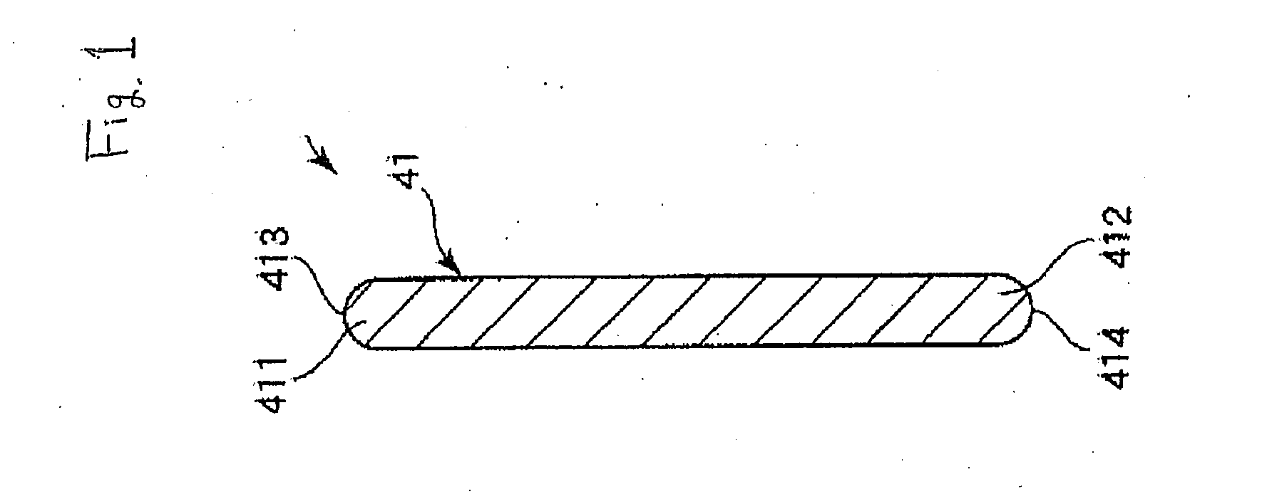
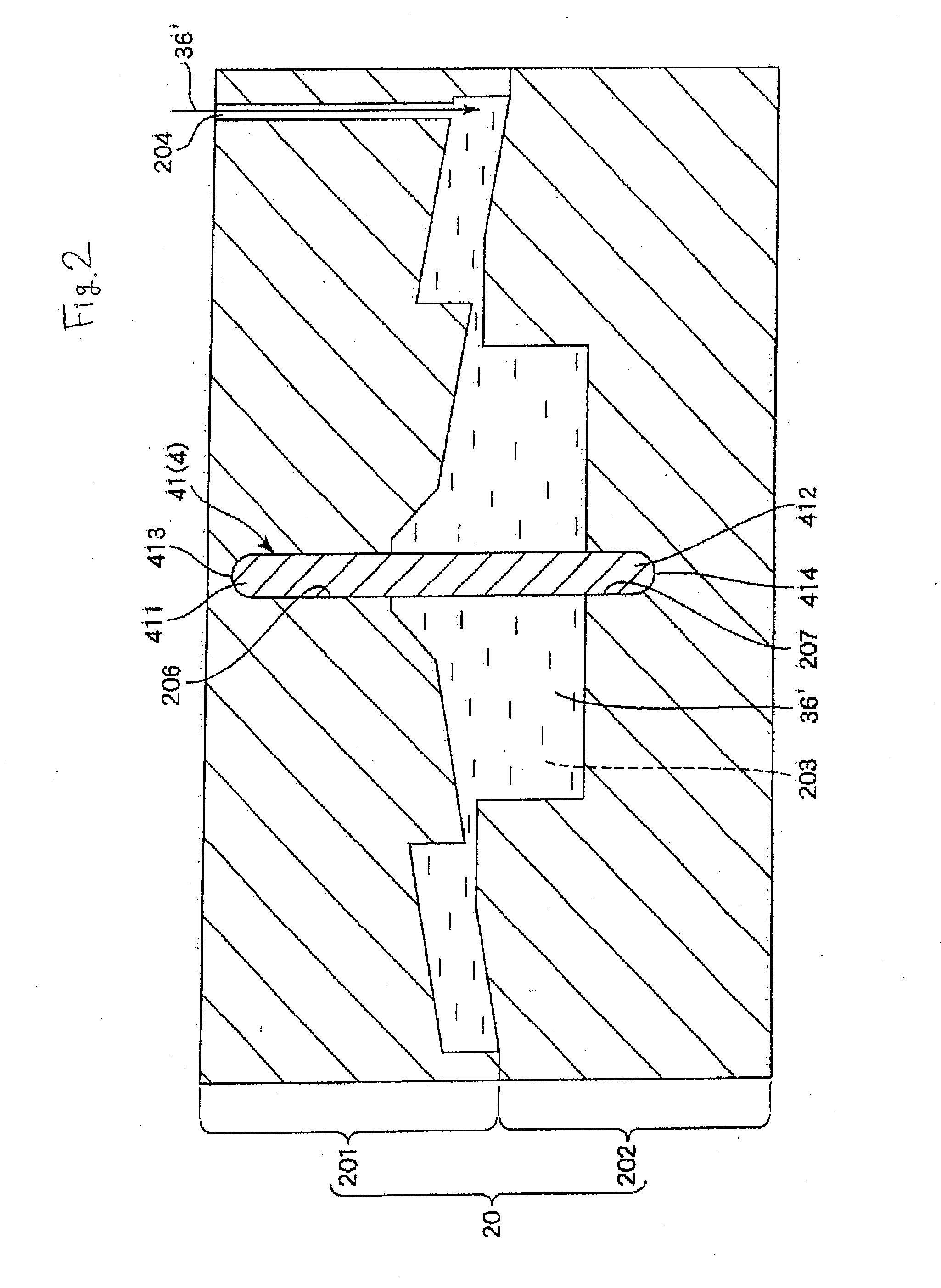
[0023]FIGS. 1 to 7 are vertical cross-sectional views sequentially showing a method of manufacturing a centrifugal pump according to a first embodiment of the invention. In the following description, the upper sides of FIGS. 1 to 10 will be referred to as “upper” and their lower sides as “lower” for convenience of explanation.

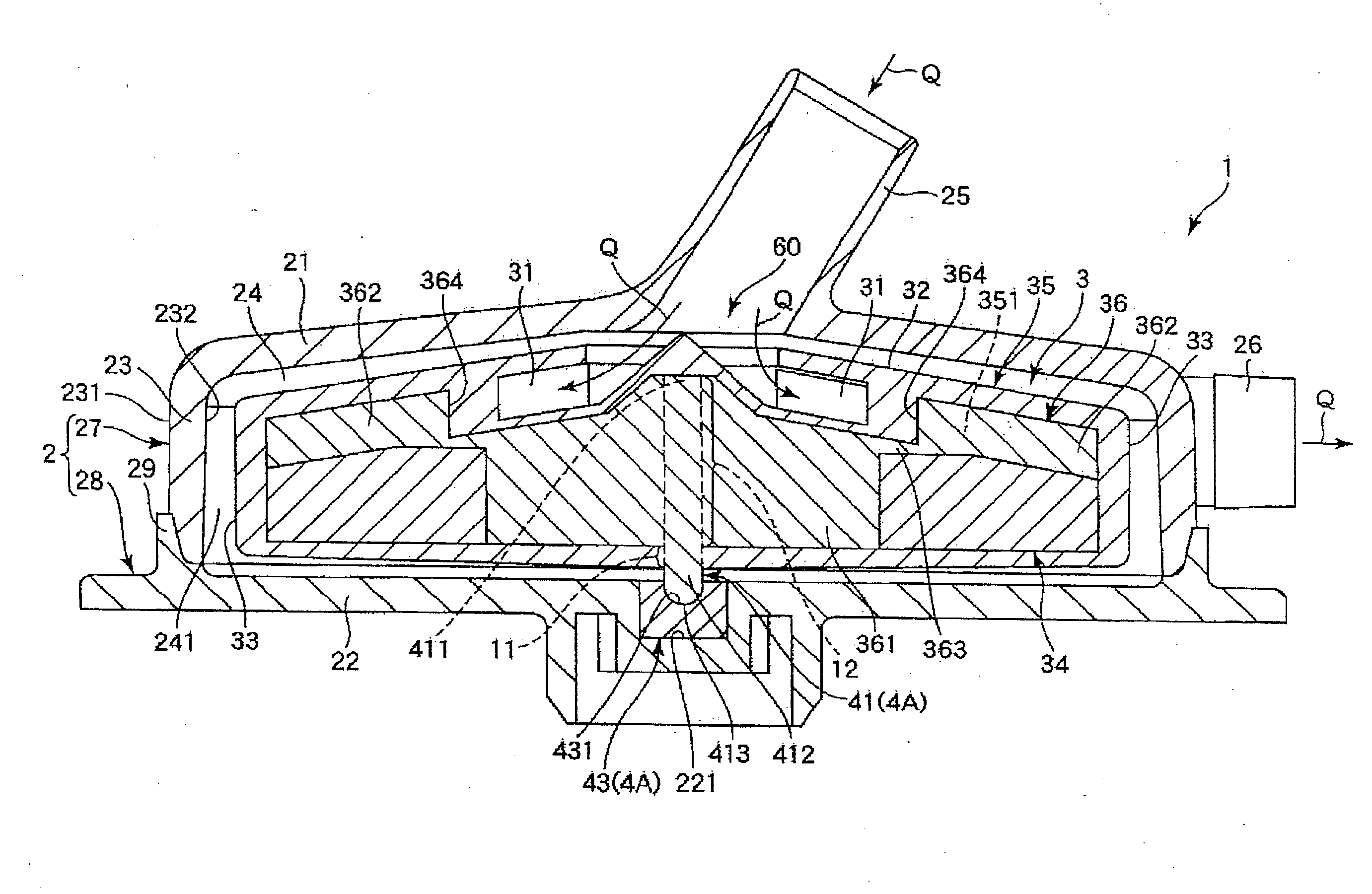
[0024]A centrifugal pump 1 shown in FIG. 7 is provided with a housing 2 constituted of a hollow body, an impeller 3 rotatably encased in the housing 2, and a support mechanism 4 supporting the impeller 3 rotatably with respect to the housing 2. Hereinafter, the configuration of each component will be described.

[0025]The overall shape of the housing 2 is a flat cylindrical shape and is constituted of an upper member 27 and a lower member 28. The upper member...


PUM

PropertyMeasurementUnit
diameteraaaaaaaaaa
diameteraaaaaaaaaa
thicknessaaaaaaaaaa

Abstract

A centrifugal blood pump reliably prevents blood from entering between an impeller and a shaft member. Pump 1 includes a pump chamber 24, a housing 2 including a blood inlet 25 and a blood outlet 26, an impeller 3 as a centrifugal force applying member rotatably encased in the pump chamber 24 and applying a centrifugal force to the blood Q by the rotation of the impeller 3. A support mechanism 4 supports impeller 3 rotatably with respect to the housing 2. The support mechanism 4 includes a rod-shaped shaft member 41 disposed at the rotation center of the impeller 3. Shaft member 41 and the impeller 3 are formed integrally with each other, as by insert molding.

Description

CROSS REFERENCE TO RELATED APPLICATIONS[0001]This application claims priority to Japanese patent application 2012-068398, filed Mar. 23, 2012, which is hereby incorporated by reference.STATEMENT REGARDING FEDERALLY SPONSORED RESEARCH[0002]Not Applicable.BACKGROUND OF THE INVENTION[0003]1. Technical Field[0004]The present invention relates to a centrifugal pump and a method of manufacturing a centrifugal pump.[0005]2. Background Art[0006]In the prior art, a blood pump for transporting blood includes a turbo-type pump for delivering blood by a centrifugal force, the pump being provided with a hollow housing, an impeller rotatably encased in the housing, and a rotation shaft being in the rotation center of the impeller (for example, see U.S. Pat. No. 5,575,630). In the blood pump disclosed in U.S. Pat. No. 5,575,630, the housing, the impeller, and the rotation shaft are constituted of separate members which are assembled to manufacture the blood pump. In assembling the blood pump, the ...

Claims


Application Information

Patent Timeline
Patent Type & Authority Applications(United States)
IPC IPC(8): F04D1/00
CPCF04D1/00Y10T29/49243F04D29/2227F05D2230/20F05D2230/21
Inventor TANAKA, SHOTAROKUMANO, KOKO
Owner TERUMO KK
Why Eureka
Try Eureka