System and method for creating a bore and implanting a bone screw in a vertebra

a bone screw and bone screw technology, applied in the field of system and method for creating a bore and implanting a bone screw in a vertebra, can solve the problems of reducing the range of motion, accelerating degenerative changes adjacent the fused vertebrae, and back pain

Inactive Publication Date: 2013-09-26
SPARTEK MEDICAL
View PDF0 Cites 10 Cited by
  • Summary
  • Abstract
  • Description
  • Claims
  • Application Information

AI Technical Summary

Benefits of technology

[0008]Systems and methods of the embodiments of the present invention include a bone cutting tool that can be used to create a bore in a vertebral body in order to implant a bone screw with the aid of bone cement. Embodiments of the bone cutting tool of the invention include at least an outer bone cutting blade and an inner rod, preferably, an outer tube with first and second bone cutting blades and an inner rod. Movement of the inner rod causes the first and second bone cutting blades to expand. Rotating the tool causes bone to be cut and a bore in which the tool is placed to expand. Continued expansion of the bone cutting blades and rotation of the tool cause the bore to expand. The expanded bore can be cylindrical due to a cylindrical shape of the bone cutting blades. Once the bore has a desired size, the bone cutting blades can be retracted and the tool removed from the bore.
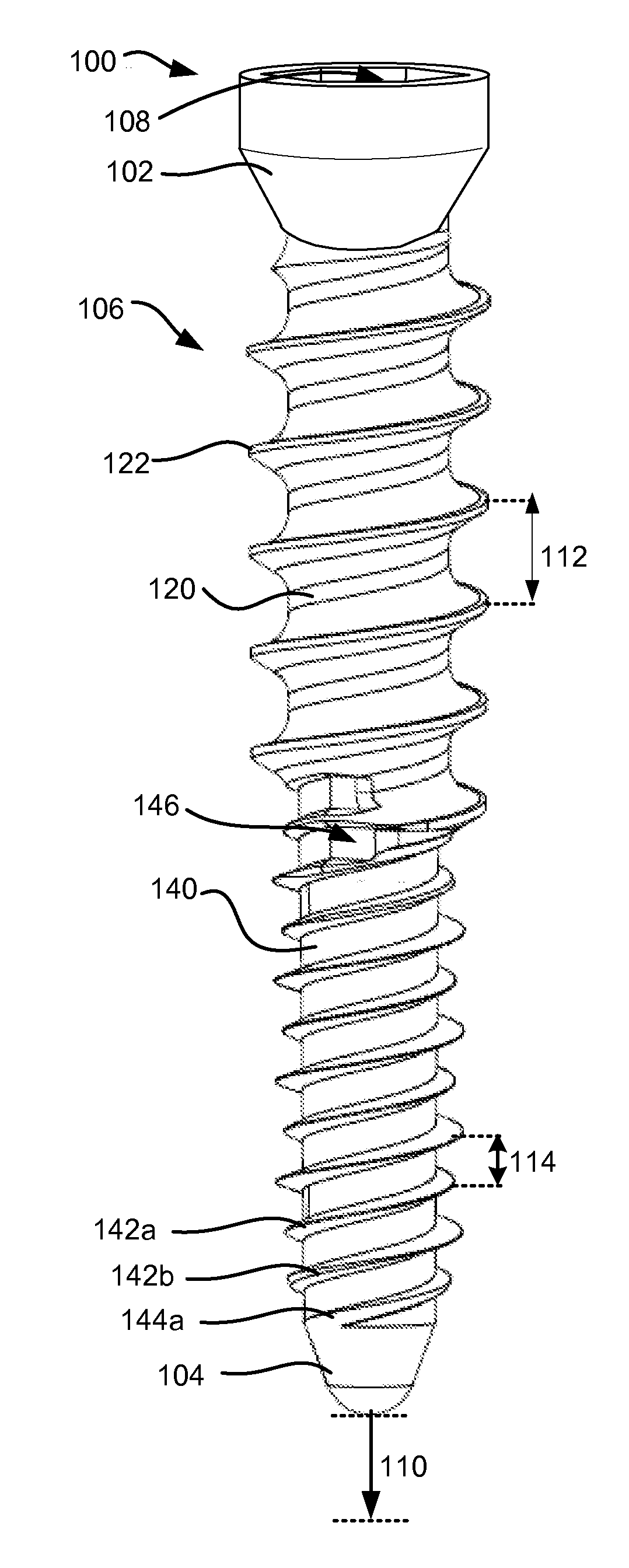
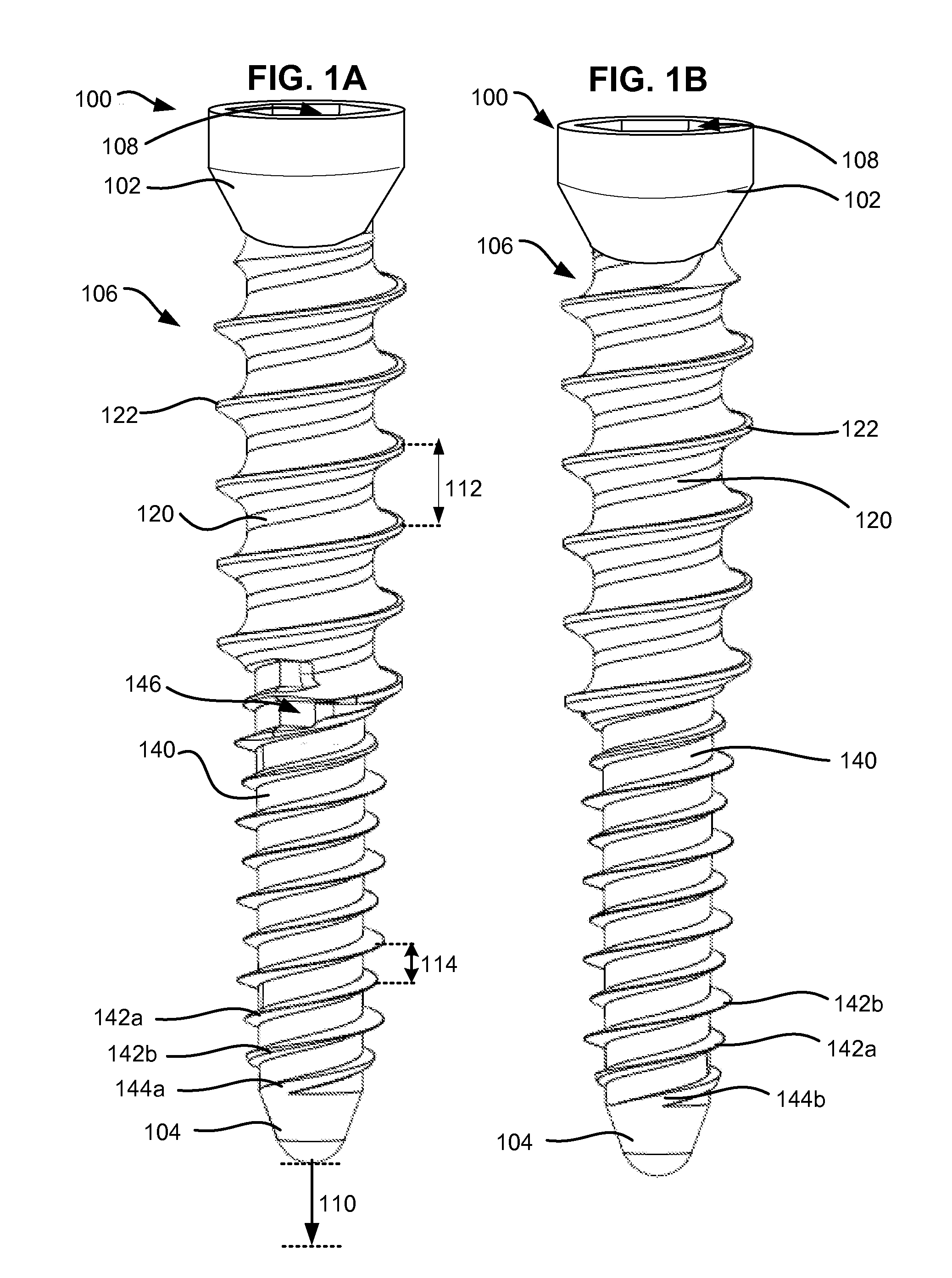
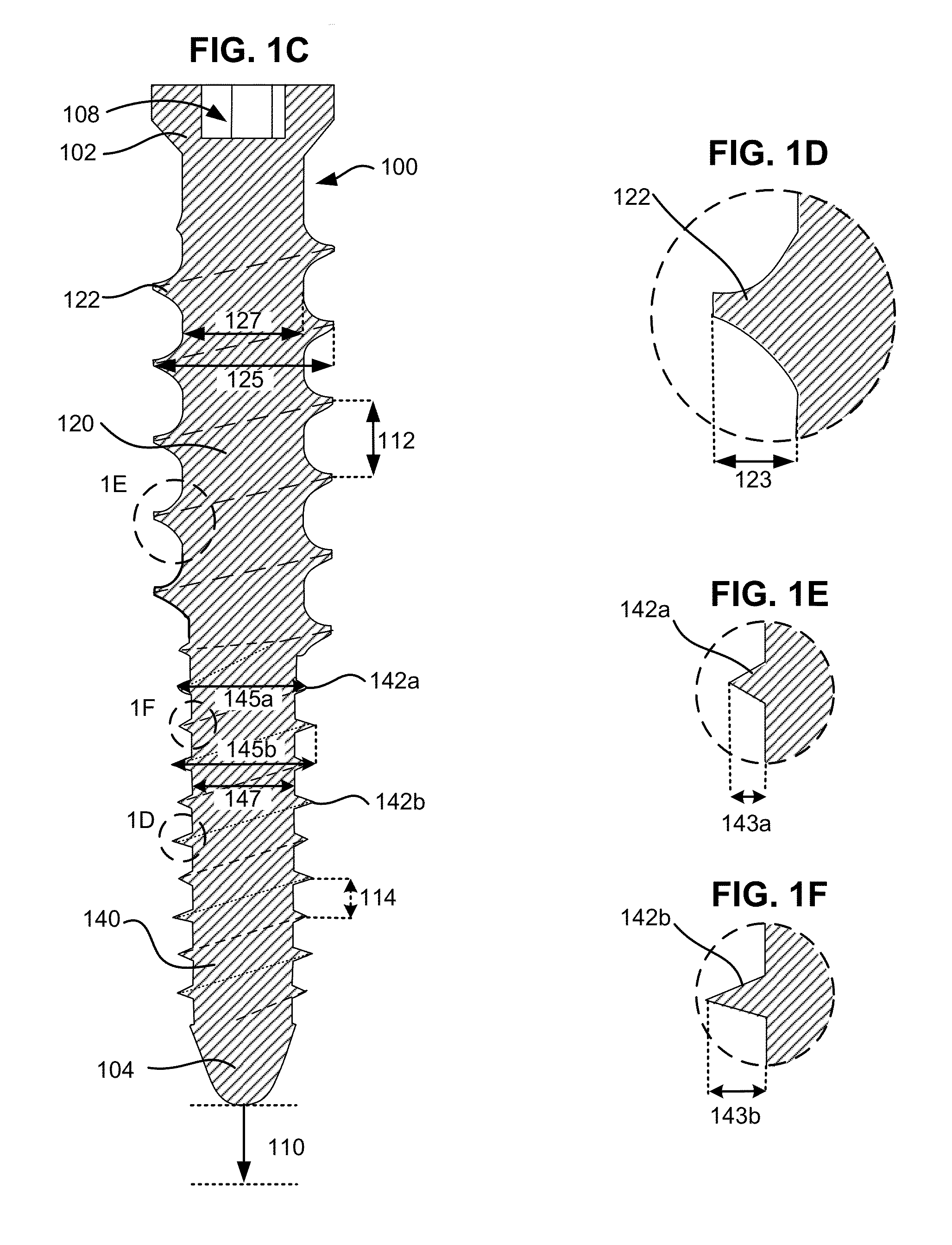
[0011]An aspect of embodiments of the invention is the ability of the bone anchor system to engage both bone and hardened bone cement with a single anchor. Another aspect of embodiments of the invention is the ability to provide a kit of versatile components suitable for particular bones of the patient and which may be customized to the anatomy and needs of a particular patient and procedure. Another aspect of the invention is to facilitate the process of implantation of the bone anchor and minimize disruption of the bone and hardened bone cement during implantation.

Problems solved by technology

Back pain is a significant clinical problem and the costs to treat it, both surgical and medical, are estimated to be over $2 billion per year.
However, spinal fusion has several disadvantages including reduced range of motion and accelerated degenerative changes adjacent the fused vertebrae.
However, such screws are poorly adapted for use in bones which have been previously treated with bone cement.

Method used


Image

  • System and method for creating a bore and implanting a bone screw in a vertebra
  • System and method for creating a bore and implanting a bone screw in a vertebra
  • System and method for creating a bore and implanting a bone screw in a vertebra

Examples


Embodiment Construction

[0035]Devices for treating the spine, including those used in spinal fusion and spinal stabilization with motion preservation, are typically secured to the spine using screws which penetrate the bone. Such screws are designed to engage the structure of the bone. However, such bones may have been treated with bone cement in a prior procedure. For example, in a kyphoplasty or vertebroplasty procedure, bone cement is injected percutaneously into a fractured or degenerated vertebra with the goal of ameliorating vertebral compression fractures. The bone cement is injected into the bone where it fills natural or surgically created voids in the cancellous bone material within the bone.

[0036]A commonly used bone cement is polymethyl methacrylate or PMMA. Bone cements may include a powder (i.e., pre-polymerized PMMA and or PMMA or MMA co-polymer beads and / or amorphous powder, radio-opacifier, initiator) and a liquid (MMA monomer, stabilizer, inhibitor). Bone cements are typically provided as...


PUM


Abstract

A system and method for implanting a bone screw in bone which includes the use of a bone cutting tool with expanding bone cutting blades that create a bore in the bone of a desired shape and size. Then a bone screw is introduced into the bore and bone cement is positioned between the bone screw and the bore to fix the position of the bone screw relative to the bone.

Description

CLAIM TO PRIORITY[0001]This application claims the benefit of priority to U.S. Provisional Patent Application No. 61 / 725,771, filed Nov. 13, 2012, entitled “SYSTEM AND METHOD FOR IMPLANTING A BONE SCREW IN A VERTEBRA”; and[0002]This application claims the benefit of priority to and is a continuation-in-part of:[0003]U.S. patent application Ser. No. 13 / 434,652, filed Mar. 29, 2012, entitled “SYSTEM AND METHOD FOR SECURING AN IMPLANT TO A BONE CONTAINING BONE CEMENT”; and[0004]U.S. patent application Ser. No. 13 / 434,674, filed Mar. 29, 2012, entitled “SYSTEM AND METHOD FOR SECURING AN IMPLANT TO A BONE CONTAINING BONE CEMENT”; and which claims the benefit of priority to:[0005]U.S. Provisional Application No. 61 / 615,639, filed Mar. 26, 2012, entitled “SYSTEM AND METHOD FOR SECURING AN IMPLANT TO A BONE CONTAINING BONE CEMENT” which all of the above applications are herein incorporated by reference in their entirety.BACKGROUND OF INVENTION[0006]Back pain is a significant clinical proble...

Claims


Application Information

Patent Timeline
Patent Type & Authority Applications(United States)
IPC IPC(8): A61B17/16
CPCA61B17/1671A61B17/1617A61B17/7001A61B17/8847A61B17/863A61B17/8635A61B17/864A61B17/8625
Inventor MITCHELL, STEVEN T.WINSLOW, CHARLES J.ZUCHERMAN, JAMES F.HSU, KEN Y.
Owner SPARTEK MEDICAL
Why Eureka
Try Eureka