
Heat integrated distillation apparatus

a distillation apparatus and heat-integrated technology, which is applied in the direction of distillation in boilers/stills, separation processes, fractional distillation, etc., can solve the problems of large amount of energy consumed, inability to obtain product, and inability to form pipe arrangements, etc., to achieve convenient maintenance of the apparatus, high energy efficiency, and optimized feed stages

Active Publication Date: 2013-10-03
TOYO ENG CORP
View PDF17 Cites 16 Cited by
  • Summary
  • Abstract
  • Description
  • Claims
  • Application Information

AI Technical Summary

Benefits of technology

The present invention improves the design of a distillation apparatus to achieve further energy savings. The invention introduces high-temperature vapor into the heat exchanger located in the lower part of the low-pressure column, and introduces fluids to the lower part of the high-pressure column, which cools the fluids and provides heat to the lower part of the low-pressure column. The heat transfer system is configured to reduce the amount of heat removed at the condenser and supply heat at the reboiler, resulting in more efficient heating and cooling. The invention also allows for easy handling of side cutting and multi-feed streams, and is easy to maintain and operate. The invention provides high energy efficiency, flexibility in design, and ease of use.

Problems solved by technology

Distillation separation is a unit operation widely applied to industrial processes in general, but consumes a large amount of energy.
1) The product cannot be obtained with side-cut stream.
As a result, no pipe arrangement can be formed to withdraw any intermediate distillate product from the inner pipe of each tube unit.
2) The feed stage where feed stream is provided cannot be optimized.
5) Maintenance of the apparatus is difficult.
This disables complete access to the desired tube unit, and maintenance thereof cannot be carried out.
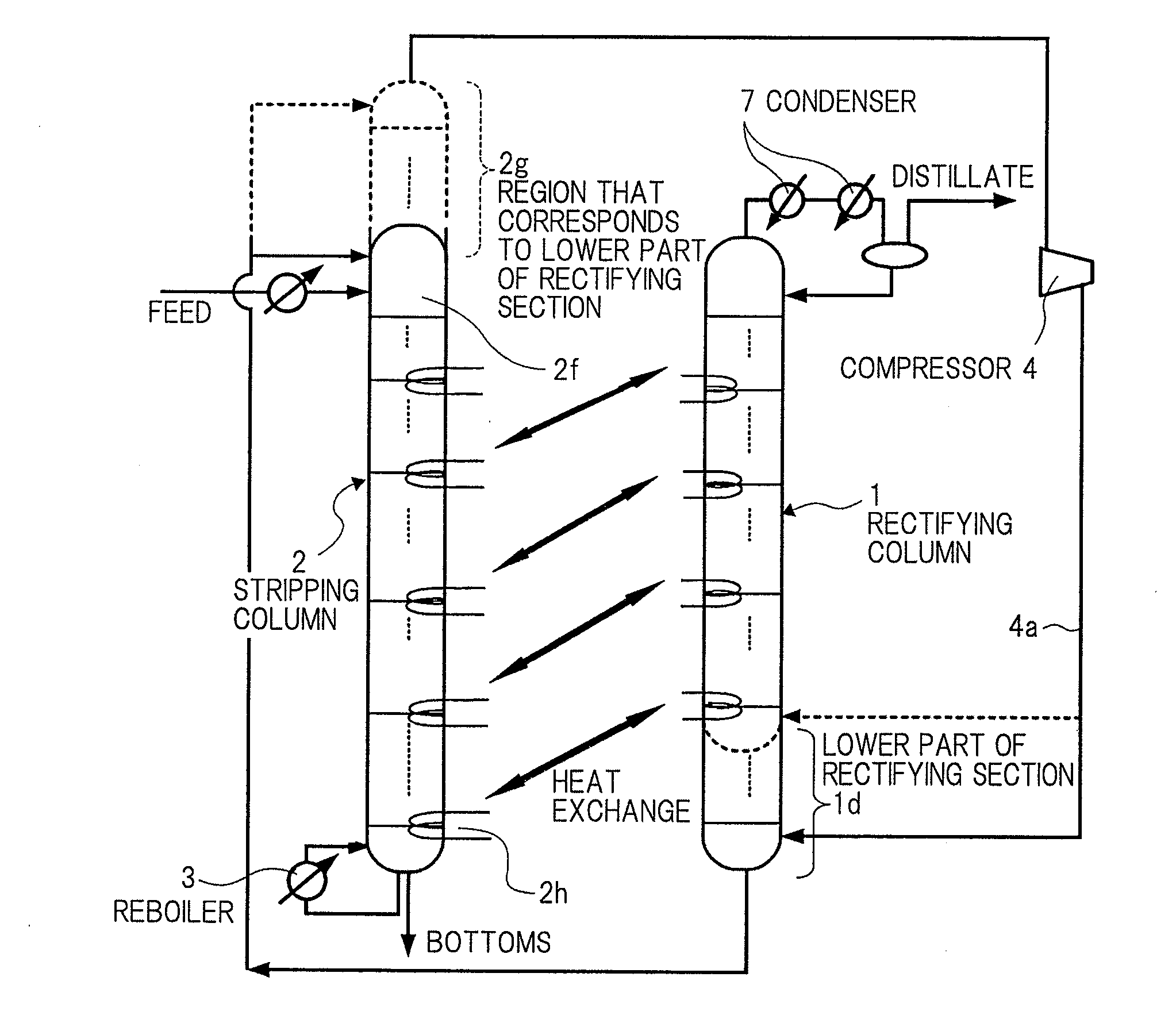
However, if outlet pipe 4a of compressor 4 is directly connected to the heat exchanging section located at the lowermost position of the rectifying section without being directly connected to the lowermost portion of the rectifying section, there will not be any gas in lower part 1d, which is located below this, of the rectifying section, and therefore, distillation operation which has liquid-vapor equilibrium as the principle of separation is not established.
Therefore, the apparatus which uses this method of connection cannot be realized.

Method used


Image

  • Heat integrated distillation apparatus
  • Heat integrated distillation apparatus
  • Heat integrated distillation apparatus

Examples


Embodiment Construction

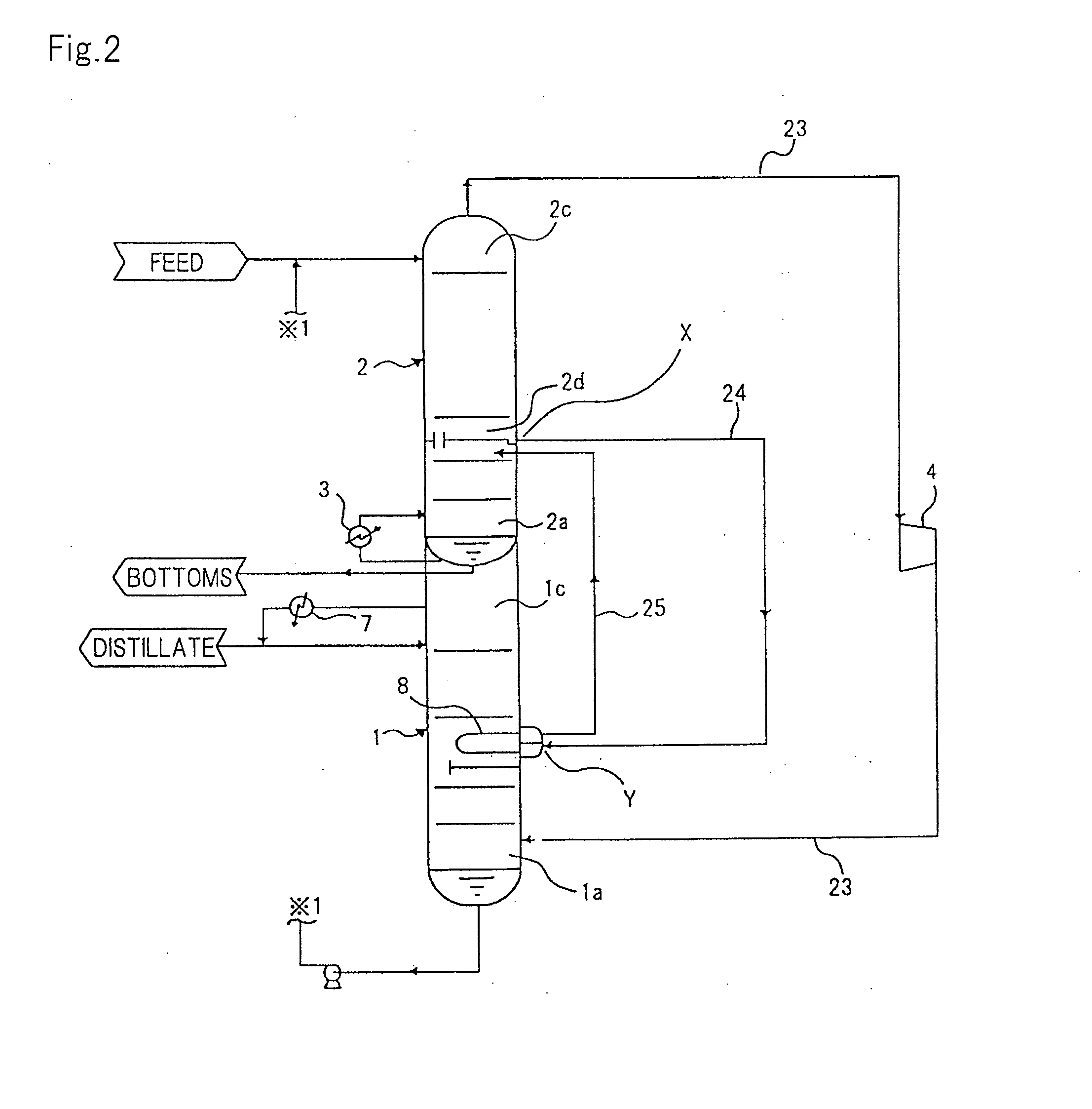
[0098]A heat integrated distillation apparatus according to the present invention has a basic feature in which a column shell (low-pressure column) that is the result of adding a region used as a stripping section extending in a vertical direction, and a region (or a rectifying section corresponding portion) that corresponds to a region locating below a side heat exchanging section at the lowermost stage among side heat exchanging sections installed in the rectifying section, and a column shell (high-pressure column) which includes a region, except for the aforementioned region that corresponds to the rectifying section of the rectifying section extending in the vertical direction, are separately provided, and the low-pressure column is located above as seen from the high-pressure column. A general distillation apparatus, which is not an internally heat integrated distillation apparatus, includes a column that is built in the vertical direction and that has a column bottom, a trayed...


PUM


Abstract

A distillation apparatus of the present invention includes high-pressure column 1 corresponding to a region above a heat exchanging section located at a lowermost part of a region including a trayed section or a packed bed section, which is used as a rectifying section; and low-pressure column 2 that is located above as seen from high-pressure column 1, which integrates a region including a trayed section or a packed bed section which is used as a stripping section, with rectifying section corresponding portion 2g that corresponds to a region locating below the heat exchanging section located at the lowermost part in the rectifying section. Rectifying section corresponding portion 2g is located on top 2c of the stripping section in low-pressure column 2 so that rectifying section corresponding portion 2g continues to the stripping section.

Description

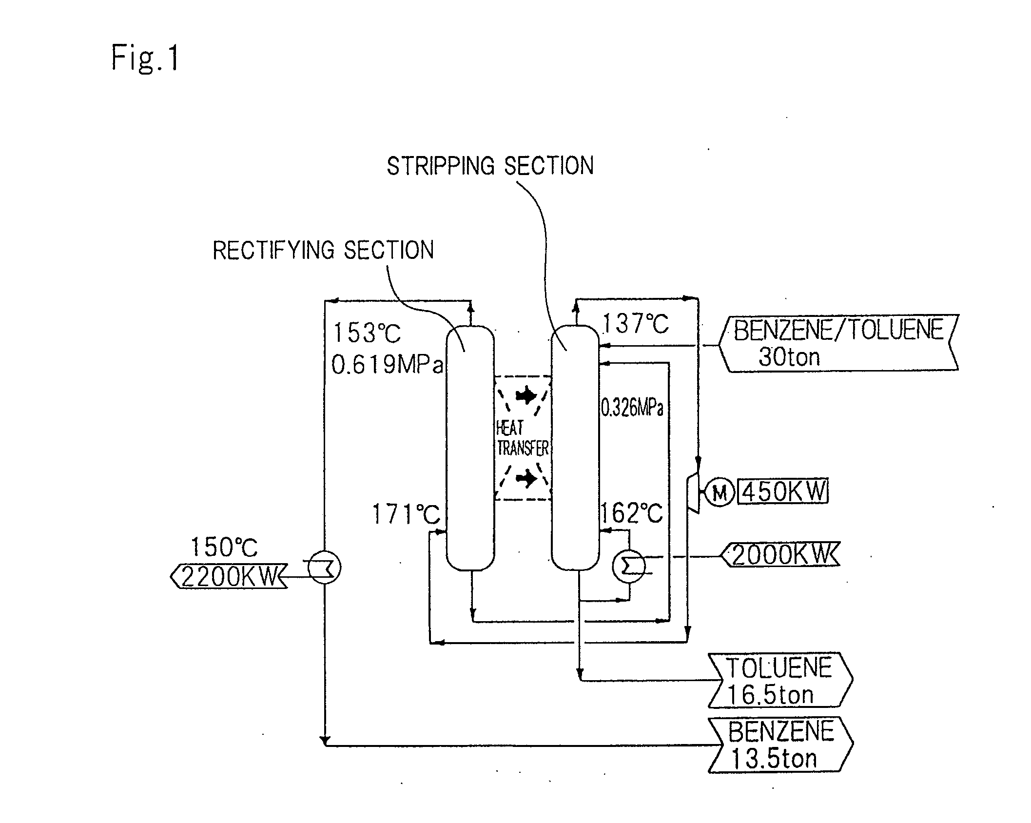
[0001]This application is based upon and claims the benefit of priority from Japanese patent application No. 2012-080525, filed on Mar. 30, 2012, the disclosure of which is incorporated herein in its entirety by reference.BACKGROUND OF THE INVENTION[0002]1. Field of the Invention[0003]The present invention relates to a distillation apparatus that carries out a distillation operation widely applied to many industrial processes, and more particularly to a heat integrated distillation apparatus.[0004]2. Description of the Related Art[0005]Distillation separation is a unit operation widely applied to industrial processes in general, but consumes a large amount of energy. In the industrial field, therefore, studies have been conducted on an energy saving distillation systems. Such studies have brought about development of a heat integrated distillation column (hereinafter, HIDiC) as a distillation apparatus that save much energy.[0006]As shown in FIG. 1, a basic system of the HIDiC has a...

Claims


Application Information

Patent Timeline
Patent Type & Authority Applications(United States)
IPC IPC(8): B01D3/00
CPCB01D1/28B01D3/007B01D3/4261B01D3/322B01D3/143B01D3/00B01D3/32
Inventor WAKABAYASHI, TOSHIHIRONAKAO, TAKATO
Owner TOYO ENG CORP
Learn More