Plasma source pumping and gas injection baffle

a technology of plasma source and gas injection, which is applied in the direction of spraying apparatus, spray nozzle, coating, etc., can solve the problems of damage to the pump, poor pumping effect, and weak application of magnetic confinement in many industrial applications

Inactive Publication Date: 2013-10-03
TOKYO ELECTRON LTD
View PDF0 Cites 9 Cited by
  • Summary
  • Abstract
  • Description
  • Claims
  • Application Information

AI Technical Summary

Problems solved by technology

Magnetic confinement has strong limitations in its applicability to many industrial applications.
However, at vacuum pressures the exhaust flow is slow, and if plasma is drawn from the plasma-containing region into the pump, then the plasma will damage the pump and / or cause other problems.
However, the device 10 as shown in FIG. 1 does not resolve the issues associated with slow exhaust.

Method used


Image

  • Plasma source pumping and gas injection baffle
  • Plasma source pumping and gas injection baffle
  • Plasma source pumping and gas injection baffle

Examples


Embodiment Construction

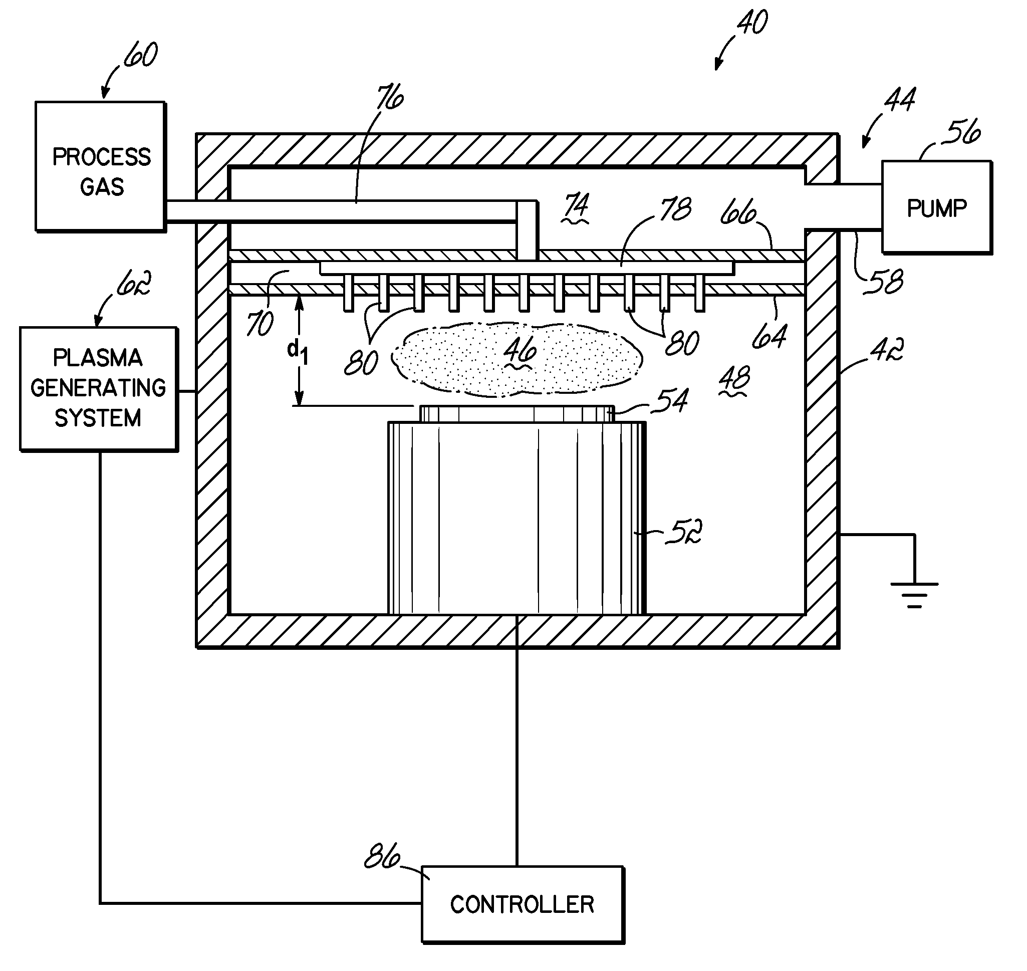
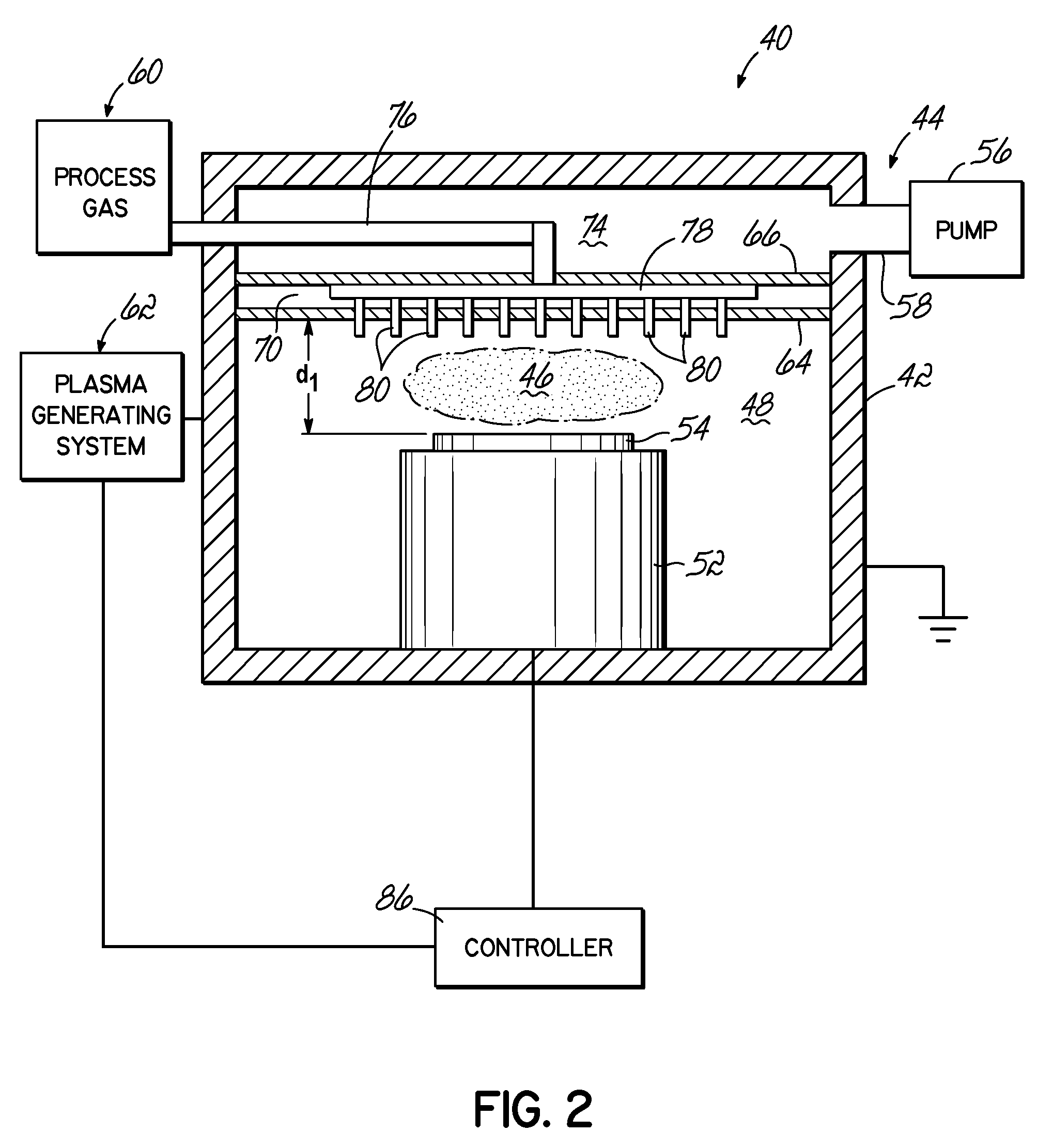
[0021]Turning now to the figures, and in particular to FIG. 2, a plasma processing system 40 with a process chamber 42 and an exhaust assembly 44 therein are provided according to one embodiment of the present invention. The process chamber 42 is configured to facilitate the formation of a plasma 46 in a process space 48, a substrate holder 52 coupled to one side of the process chamber 42 configured to support a substrate 54 thereon, and a vacuum pumping system 56 coupled to the process chamber 42 via a pumping port 58 and configured to evacuate process gases from the process space 48. As alluded to above, the substrate 54 is positioned on one end of the process chamber 42 while a process gas injection source 60 is proximate the opposing side of the process chamber 42 and the plasma 46 is ignited therebetween by a plasma generation system 62.

[0022]The plasma generation system 62 may comprise one or more of a capacitively coupled plasma (“CCP”) system, an inductively coupled plasma (...


PUM

PropertyMeasurementUnit
distanceaaaaaaaaaa
distanceaaaaaaaaaa
thickaaaaaaaaaa

Abstract

A plasma processing system. The processing system comprises a process chamber having first and second ends arranged such that the first end opposes the second end. A substrate support is positioned at the first end of the process chamber and is configured to support a substrate. An exhaust system is positioned proximate the second end of the process chamber and draws a vacuum on the process chamber. Between the exhaust system and substrate support there is a plurality of super-Debye openings, and between the exhaust system and the plurality of super-Debye openings is a plurality of sub-Debye openings. The super-Debye openings are configured to limit diffusion of plasma while the sub-Debye openings are configured to quench plasma.

Description

FIELD OF THE INVENTION[0001]The present invention relates generally to an apparatus for plasma processing a substrate and, more particularly, to an apparatus for resisting movement of plasma from plasma-processing region.BACKGROUND OF THE INVENTION[0002]Plasma processing is often used under circumstances where it is beneficial to restrict the presence of the plasma to a certain plasma-containing region in a processing chamber while maintaining the ability to flow gases through the plasma-containing region. Several methods of plasma containment are known, including, for example, magnetic confinement, inertial confinement, and structural confinement by solid or nearly-solid barriers. Inertial confinement is operable for only short periods of time and has been shown useful only in power generating and explosive devices. Magnetic confinement has strong limitations in its applicability to many industrial applications. Because of these and other shortcomings of inertial and magnetic confi...

Claims


Application Information

Patent Timeline
Patent Type & Authority Applications(United States)
IPC IPC(8): B44C1/22B05B1/00B05C11/00B05C13/00
CPCH01J37/32504H01J37/32935H01J37/32834H01J37/32633
Inventor CHEN, LEEFUNK, MERRITT
Owner TOKYO ELECTRON LTD
Why Eureka
Try Eureka