
X-Ray Diffraction Measuring Apparatus Having Debye-Scherrer Optical System Therein, and an X-ray Diffraction Measuring Method for the Same

a technology of x-ray diffraction and optical system, which is applied in the direction of material analysis using radiation diffraction, instruments, measurement devices, etc., can solve the problems of remarkable lowering of resolution power, and increasing angular error, so as to solve the lowering of measuring strength or intensity or deterioration of resolution power. , the effect of superior

Inactive Publication Date: 2009-04-02
RIGAKU CORP
View PDF9 Cites 5 Cited by
  • Summary
  • Abstract
  • Description
  • Claims
  • Application Information

AI Technical Summary

Benefits of technology

[0012]As is apparent from the above, according to the present invention, it is possible to achieve an extremely superior effect, i.e., providing an X-ray diffraction measuring apparatus comprising the Debye-Scherrer optical system therein and an X-ray diffraction measuring method for the same, for dissolving the reduction of scattering ray (i.e., the diffraction X-ray) due to the eclipse (e.g., shielding) thereof, thereby dissolving the lowering of measuring strength or intensity or deterioration of resolution power, and further without lowering of the resolution power thereof depending on size of the sample.

Problems solved by technology

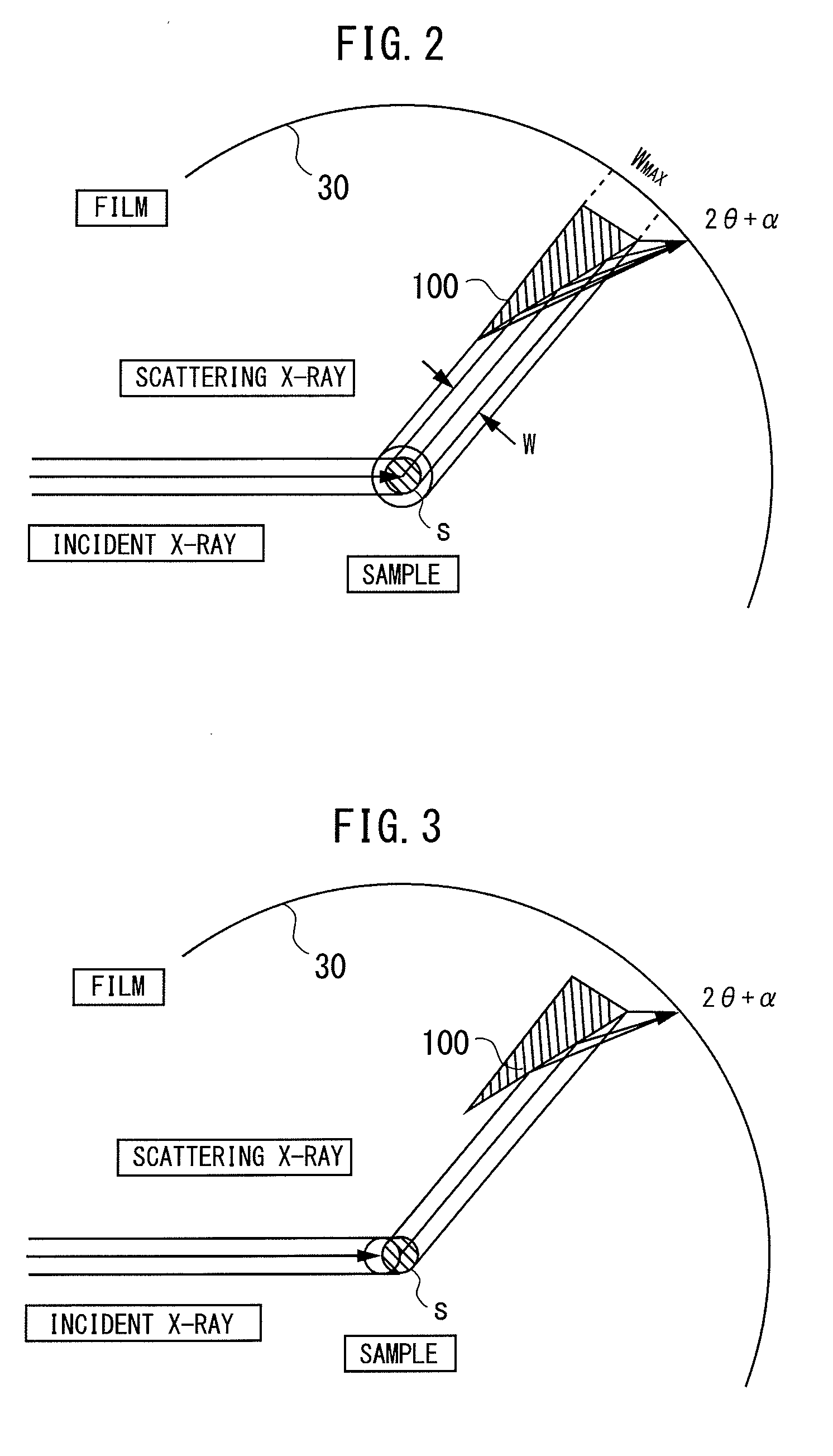
However, with such the method of the conventional arts mentioned above, although the details thereof will be mentioned later, the analyzer mentioned above, being provided for reducing the background, brings about an eclipse (e.g., shielding) of the scattering rays (e.g., diffraction X-rays), and thereby this results into a lowering of measuring strength or intensity.
Also, there are other problems: i.e., an increase of angular error due to shift or deviation of the position for mounting the sample thereon, and further a remarkable lowering of resolution power due to a size of the sample, etc.

Method used


Image

  • X-Ray Diffraction Measuring Apparatus Having Debye-Scherrer Optical System Therein, and an X-ray Diffraction Measuring Method for the Same
  • X-Ray Diffraction Measuring Apparatus Having Debye-Scherrer Optical System Therein, and an X-ray Diffraction Measuring Method for the Same
  • X-Ray Diffraction Measuring Apparatus Having Debye-Scherrer Optical System Therein, and an X-ray Diffraction Measuring Method for the Same

Examples


Embodiment Construction

[0022]Hereinafter, embodiments according to the present invention will be fully explained by referring to the attached drawings.

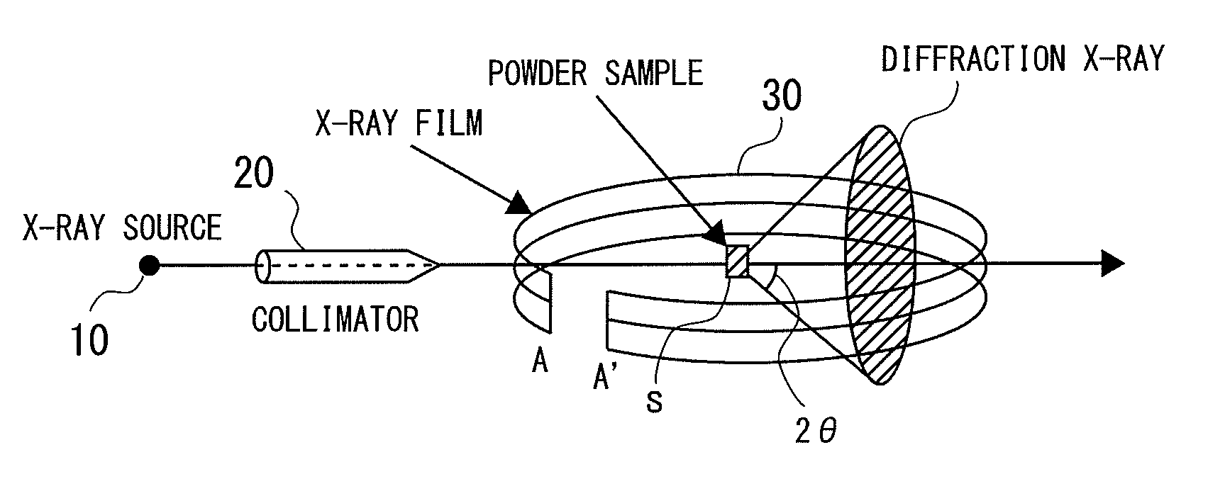
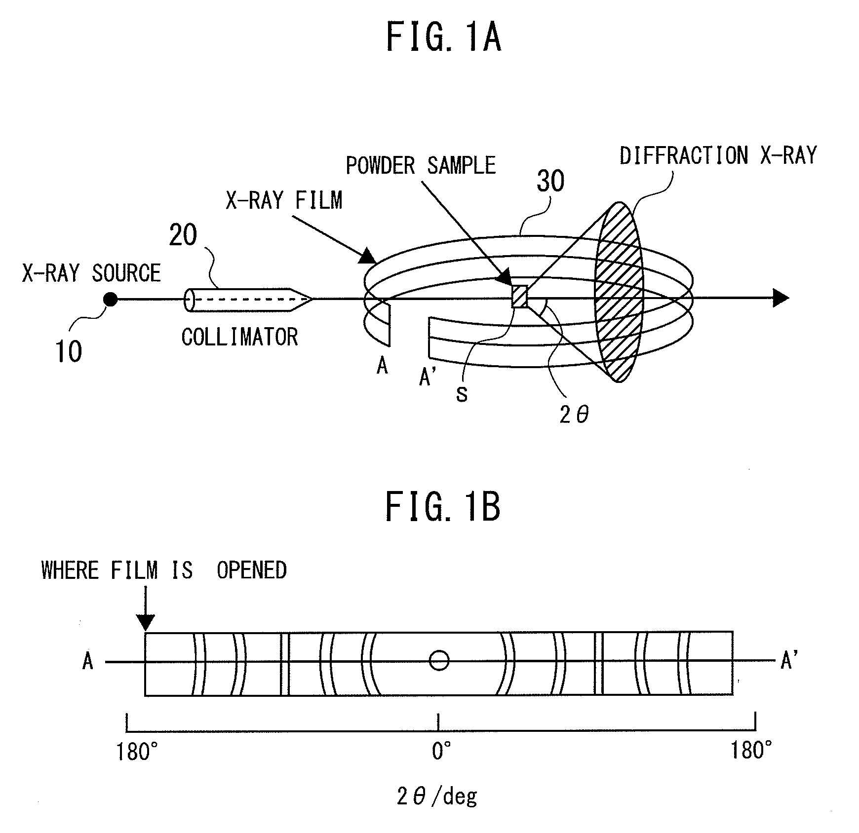
[0023]First of all, FIG. 1A attached herewith shows an outlook configuration of an X-ray diffraction measuring apparatus having the Debye-Scherrer optical system therein, according to an embodiment of the present invention, wherein a monochromatic characteristic X-ray, which is emitted from an X-ray source 10 made of an X-ray tube, for example, is irradiated upon a sample S of polycrystalline substance, after being collimated into a parallel beam of a predetermined diameter through a collimator 20. As a result thereof, this irradiated X-ray scatters over a predetermined angle 2θ around that sample S, as an X-ray diffracted by that sample S of polycrystalline substance, and thereby being irradiated upon an X-ray detection means 30, being constructed with an X-ray film, which is cylindrically disposed on the periphery thereof, around that sample S, etc. As a ...


PUM


Abstract

An X-ray diffraction measuring apparatus equipped with Debye-Scherrer optical system therein, comprises a means for generating a characteristic X-ray to be irradiated upon a sample to be measured; an X-ray detector means being disposed to surround that sample around; and a focusing means, being disposed between the sample and the X-ray detector means, for collecting an X-ray scattering from the sample covering over a predetermined angle, in a peripheral direction, around the sample, and thereby irradiating it upon the X-ray detector means.

Description

BACKGROUND OF THE INVENTION[0001]The present invention relates to an X-ray diffraction measuring apparatus for analyzing powder-like crystals or the like, with using an X-ray, and in particular, it relates to an X-ray diffraction measuring apparatus building up a Debye-Scherrer optical system therein, and also an X-ray diffraction measuring method for the same.[0002]In general, various kinds of X-ray diffraction measuring apparatuses are already known, comprising the Debye-Scherrer optical system therein, for analyzing a sample of powder-like crystals, through measuring the diffraction rings (i.e., Debye rings), which can be obtained from that sample, in an angular direction around that, while irradiating a monochromatic X-ray thereupon.[0003]By the way, with such X-ray diffraction measuring apparatus, comprising the Debye-Scherrer optical system therein, due to excessive scattering X-rays, such as, stray radiations, inelastic scattering, fluorescence X-rays, etc., for example, with...

Claims


Application Information

Patent Timeline
IPC IPC(8): G01N23/20
CPCG01N23/20G01N23/207
Inventor OZAWA, TETSUYAMATSUO, RYUJIFUJINAWA, GOECHIZENYA, AKIRA
Owner RIGAKU CORP
Learn More