Method And Apparatus For Phase-Controlling A Load

a technology of phase control and load, applied in the direction of electric variable regulation, process and machine control, instruments, etc., can solve problems such as current spikes

Active Publication Date: 2013-10-03
LUTRON TECH CO LLC
View PDF3 Cites 33 Cited by
  • Summary
  • Abstract
  • Description
  • Claims
  • Application Information

AI Technical Summary

Benefits of technology

[0008]A load control device may control the amount of power provided to a load utilizing a phase control signal that operates in two or more of reverse phase control mode, center phase control mode, and forward phase control mode. For example, a load control device may be configured to control an amount of power delivered from an alternating current (AC) power source to an electrical load. The load control device may include a bidirectional semiconductor switch and a controller. The bidirectional semiconductor switch may be configured to be coupled between the AC power source and the electrical load. The controller may be operatively coupled to the bidirectional semiconductor switch. The controller may be configured to determine that the electrical load should be operated in a forward phase-control mode via a phase control signal. After determining to operate the electrical load in the forward phase-control mode via the phase control signal, the controller may provide the phase control signal in a reverse phase-control mode for a predetermined period of time to the electrical load. Subsequently, the controller may be configured to switch the phase control signal to the forward phase-control mode and provide the phase control signal in the forward phase-control mode to the electrical load. The phase control signal in the reverse phase-control mode may be utilized to charge a bus capacitor of the load. The predetermined amount of time may be approximately equal to a length of an AC line cycle of the AC power source, for example.
[0009]A load control device including a controller may be configured to receive a command to turn on. The controller may provide a first line cycle of a phase control signal using a reverse phase control technique to the electrical load. The controller may provide a second line cycle of the phase control signal using a center phase control technique to the electrical load. The controller may provide a third line cycle of the phase control signal using a forward phase control technique to the electrical load. A conduction time of the first line cycle, the second line cycle, and the third line cycle may be the same. A root mean square (RMS) voltage value of the first line cycle, the second line cycle, and the third line cycle may be the same. The controller may provide a plurality of line cycles of the phase control signal using the center phase control technique to the electrical load, for example, prior to providing the third line cycle of the phase control signal using the forward phase control technique to the electrical load.

Problems solved by technology

If the capacitor is not charged, then the use of a forward phase-control dimming technique may cause a current spike, which, for example, may occur at start-up when the capacitor is fully dissipated.

Method used


Image

  • Method And Apparatus For Phase-Controlling A Load
  • Method And Apparatus For Phase-Controlling A Load
  • Method And Apparatus For Phase-Controlling A Load

Examples


Embodiment Construction

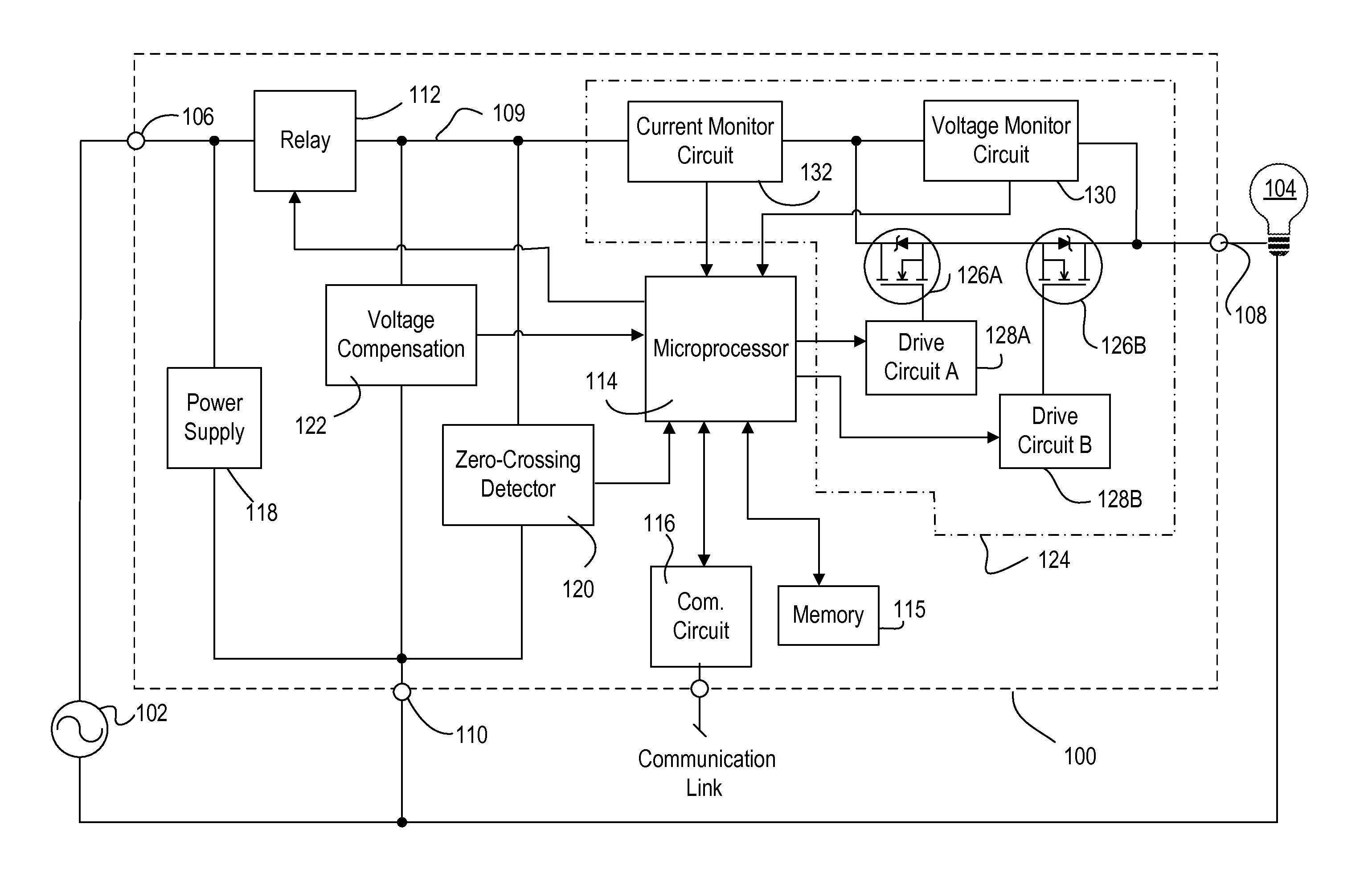
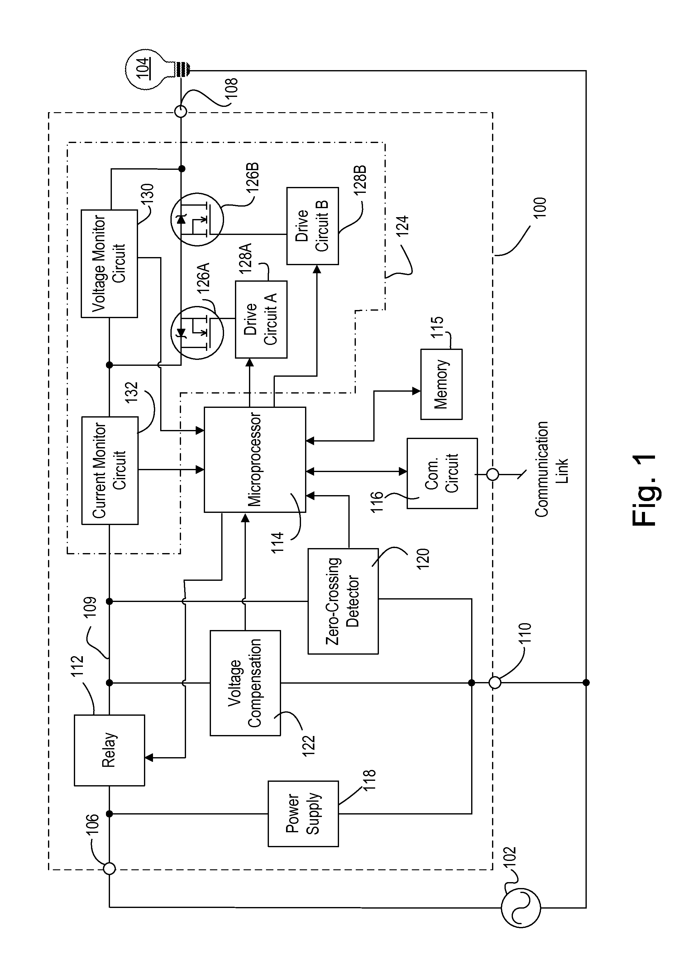
[0022]FIG. 1 is a simplified block diagram of an example load control device (e.g., load control device 100). The load control device 100 may be coupled between a hot reference of an alternating current (AC) power source 102 (e.g., 120 V, 60 Hz) and a load 104 via a hot terminal 106 and a dimmed hot terminal 108, respectively. The load 104 may be coupled between the 108 terminal and a neutral reference of the AC power source 102. The load 104 may be a lighting load, for example, an incandescent lighting load, a low voltage lighting load including a magnetic low voltage transformer, an electronic low voltage transformer, a fluorescent light source, an LED light source, or any other suitable type of lighting load. The load 104 may comprise a motor load, such as a fan or a motorized window treatment. The load control device 100 may comprise a neutral terminal 110, which may be coupled to the neutral reference of the AC power source 102.

[0023]The load control device 100 may comprise an ...


PUM


Abstract

A load control device may control the amount of power provided to an electrical load utilizing a phase control signal that operates in a reverse phase control mode, a center phase control mode, and a forward phase control mode. A load control device may be configured to determine that the electrical load should be operated via a phase control signal operating in a forward phase-control mode. After determining to operate the electrical load via the phase control signal in the forward phase-control mode, the load control device may provide the phase control signal in a reverse phase-control mode for a predetermined period of time to the electrical load, for example, to charge a bus capacitor of the electrical load. Subsequently, the load control device may be configured to provide the phase control signal in the forward phase-control mode to the electrical load.

Description

CROSS-REFERENCE TO RELATED APPLICATIONS[0001]This application claims the benefit of Provisional U.S. Patent Application No. 61 / 616,460, filed Mar. 28, 2012, the disclosure of which is hereby incorporated herein by reference.BACKGROUND[0002]Load control devices, such as dimmer switches and dimming modules, for example, may be configured to control an amount of power provided from an alternating current (AC) power source to a load, such as a lighting load, for example. Such load control devices may employ a bidirectional semiconductor switch that is coupled in series electrical connection between the AC power source and the load. The bidirectional semiconductor switch may be controlled to be conductive and non-conductive for portions of a half-cycle of the AC power source, for example, to control the amount of power delivered to the load (e.g., using a phase-control dimming technique). For example, the bidirectional semiconductor switch may comprise one semiconductor switch, such as, ...

Claims


Application Information

Patent Timeline
Patent Type & Authority Applications(United States)
IPC IPC(8): G05F5/00H05B44/00
CPCG05F5/00H05B33/0815H02M5/297Y02B20/346H05B39/048Y02B20/00Y02B20/30H05B45/37
Inventor HAUSMAN, JR., DONALD F.NEWMAN, JR., ROBERT C.SALVESTRINI, CHRISTOPHER J.
Owner LUTRON TECH CO LLC
Why Eureka
Try Eureka