Contact test device

Active Publication Date: 2013-10-03
SEIKEN
View PDF5 Cites 16 Cited by
  • Summary
  • Abstract
  • Description
  • Claims
  • Application Information

AI Technical Summary

Benefits of technology

[0042]According to the first aspect of the invention, the plate-like guide portion formed on the plunger is guided by a guide groove formed in the first block, so that guide groove can be machined relatively readily and in high precision by a dicing saw or the like. This makes it possible to break through the difficulty in machining the plunger guide hole which has hampered in minimizing an array distance of the probes and in arraying a large number of arrays. Accordingly, it is possible to provide the contact test device (testing head) accommodating to narrowing of pitch of terminals or electrodes of a test electronic parts and to multi-polarization without increasing the cost.
[0043]Still further, the guide groove can be formed in high precision readily by the dicing saw even if ceramics is used for the blocks composing the socket, so that it is possible to manufacture the high precision contact test device.
[0044]According to the second aspect of the

Problems solved by technology

Due to that, it has become cumbersome to manufacture a contact test device such as a test head in which a large number of such probes is arrayed.
Still further, due to a drop of contact pressure with each of the termin

Method used


Image

  • Contact test device
  • Contact test device
  • Contact test device

Examples


Embodiment Construction

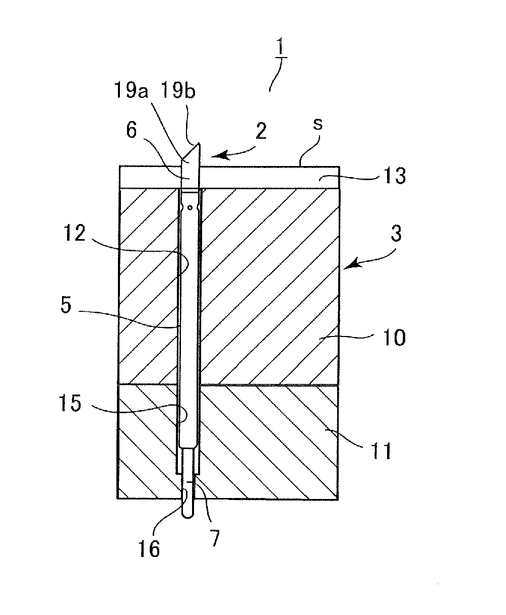
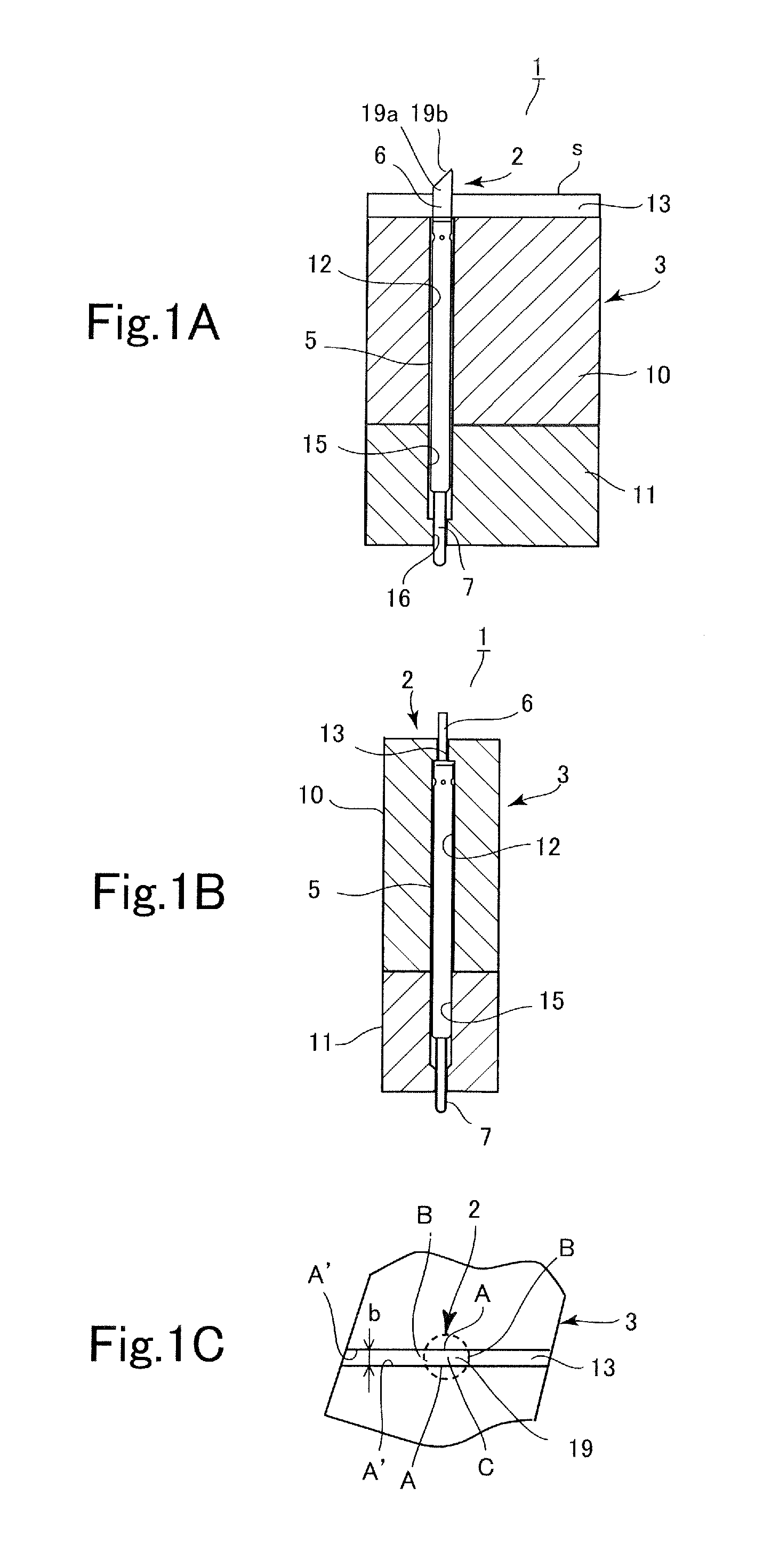
[0092]An embodiment of the present invention will be described below with reference to the drawings. As shown in FIG. 1, a contact test device 1 of the present embodiment includes a contact probe 2 made from conductive metal, and a socket 3 made from an insulating material into which the probe 2 is fitted. The probe 2 includes a tube 5, a plunger 6 which projects out of one end of the tube 5 and which is secured in a body to the tube 5, and a abutting member 7 which projects movably out of another end of the tube 5 due to a spring contractively interposed between the abutting member 7 and the plunger 6.

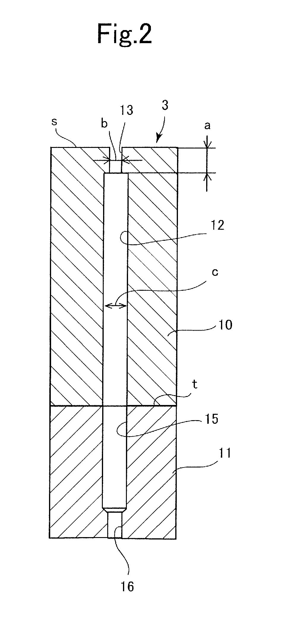
[0093]The socket 3 is composed of blocks 10 and 11 by being divided into two parts as shown in detail in FIG. 2 (the number of blocks is not limited to be two, and may be three or more or one). These blocks are provided with cylindrical retaining holes for retaining the probe such that they are aligned. Although these blocks 10 and 11 are not limited to be used as upper and lower bloc...


PUM


Abstract

Because a guide hole that guides a plunger of a probe requires cumbersome machining of a hole, it is difficult to accommodate to narrowing of pitch and multi-polarization of terminals or electrodes. A probe (2) is fitted into cylindrical retaining holes (12 and 15) formed in upper and lower blocks (10 and 11). The plunger (6) of the probe (2) has a plate-like guide portion (19a), and an edge contact portion (19b). The bottomed retaining hole (12) is formed in the upper block (10) from a lower part thereof and a guide groove (13) is formed from an upper surface (s) thereof. The guide portion (19a) is guided movably vertically while being stopped from turning and from slipping out by the guide groove (13).

Description

TECHNICAL FIELD[0001]The present invention relates to a contact test device for use in functional tests of a test electronic parts by contacting with each terminal (electrode pad) or an electrode of the test electronic parts, and more specifically to a contact test device (test head) suitable for Kelvin testing in which two current supplying and voltage monitoring probes are brought into contact with each terminal or electrode described above.BACKGROUND ART[0002]A pitch between metallic connecting terminals (electrode pad) extended from each side of a rectangular QFP (Quad Flat Package) is being narrowed lately more and more from 0.8 mm to 0.65 mm, 0.5 mm and 0.4 mm. An electrode pitch of a semiconductor product in which electrodes (terminals) called peripherals are disposed around a rectangular silicon wafer is also being narrowed from 100 μm to 65 μm, 50 μm, and 40 μm. Then, a probe that is brought to come into contact with such terminal whose pitch is narrowed is required to thin...

Claims


Application Information

Patent Timeline
IPC IPC(8): G01R1/067
CPCG01R1/0466H01R13/24G01R1/06738G01R1/06711G01R1/06722H01R2201/20G01R1/07357G01R1/067G01R31/26
Inventor TOMIOKA, HIROYUKI
Owner SEIKEN
Why Eureka
Try Eureka