Eureka AIR delivers breakthrough ideas for toughest innovation challenges, trusted by R&D personnel around the world.

Electrically Operated Turf Stacking System For Sod Harvesting Machine

Active Publication Date: 2013-10-03
FIREFLY AUTOMATIX
View PDF15 Cites 2 Cited by
  • Summary
  • Abstract
  • Description
  • Claims
  • Application Information

AI Technical Summary

Benefits of technology

The present invention is a stacking mechanism for sod harvesting machines that uses electrical actuators to stack slabs of sod. This mechanism allows for precise and fast operation. Additionally, it provides temporary pallet support wings to enable continuous stacking even while another pallet is being dropped. The sod harvesting machine also includes a pallet support structure which includes a primary support to support a pallet and temporary pallet support wings to keep the new pallet in place while the full pallet is lowered to the ground. This results in a more efficient and efficient sod harvesting process.

Problems solved by technology

This slow response time limits the speed at which hydraulically powered stacking heads can be used while still providing accurate stacking of the slabs.
However, these servo-hydraulic control valves are significantly more expensive to install because they are manufactured with very small clearances and tight tolerances.
As a result, servo-hydraulic valves are generally considered to be too expensive for sod harvesting equipment.
When using hydraulic valves, it is also difficult to suppress the vibrations caused by the movements of the stacking head.
Using this additional roller is undesirable because of its added weight and cost.
Additionally, proportional valves typically do not have built in feedback mechanisms that give the controller information about the valve spool position.
As such, it is difficult for the controller to determine when the valve is not functioning properly without adding additional sensors to the system.
When rotary hydraulic motors are used, the angular position of the stacking head cannot be adequately controlled to hold the stacking heads in place when operating on fields that are sloped.
For example, when operating on sloped fields, the stacking head can drift out of position leading to stacking errors.
If the stacking head drifts out of position when dwelling over the conveyor waiting for a slab to come into position, it can damage the head and the conveyor when it tries to pick up the slab.
An additional difficulty with hydraulic systems is that hydraulic flow losses in plumbing and valves are strongly dependent on temperature.
This warm up period wastes fuel.
Linear type hydraulic actuators (cylinders) have internal and external seals that are adversely affected by high velocity moves.
The combination of high cycle rates on the order of 2400 per hour and high velocities lead to fairly short lives and the onset of leaking after a few months operation.
In addition to the difficulties of designing a hydraulic based stacking head that can stack slabs quickly and accurately, such systems are also difficult and expensive to maintain.
For example, to achieve desired speeds and accuracy, the hydraulic system requires more complex and expensive components.
Also, operating the stacking head at such speeds leads to more frequent service and replacement of components.
Another problem that exists with current stacking mechanisms is that, due to the way that the slabs are stacked, the stack tends to become rounded on top.
This rounding increases the risk that the stack will tip over or split apart.
This step of lifting the pallet is slow and requires the harvesting machine to temporarily stop until the full pallet has been compacted, dropped, and replaced.

Method used


Image

  • Electrically Operated Turf Stacking System For Sod Harvesting Machine
  • Electrically Operated Turf Stacking System For Sod Harvesting Machine
  • Electrically Operated Turf Stacking System For Sod Harvesting Machine

Examples


Embodiment Construction

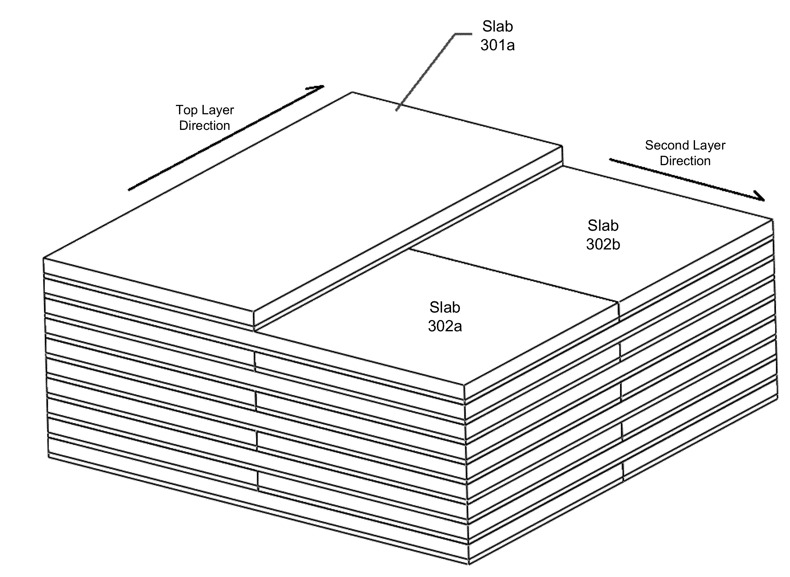
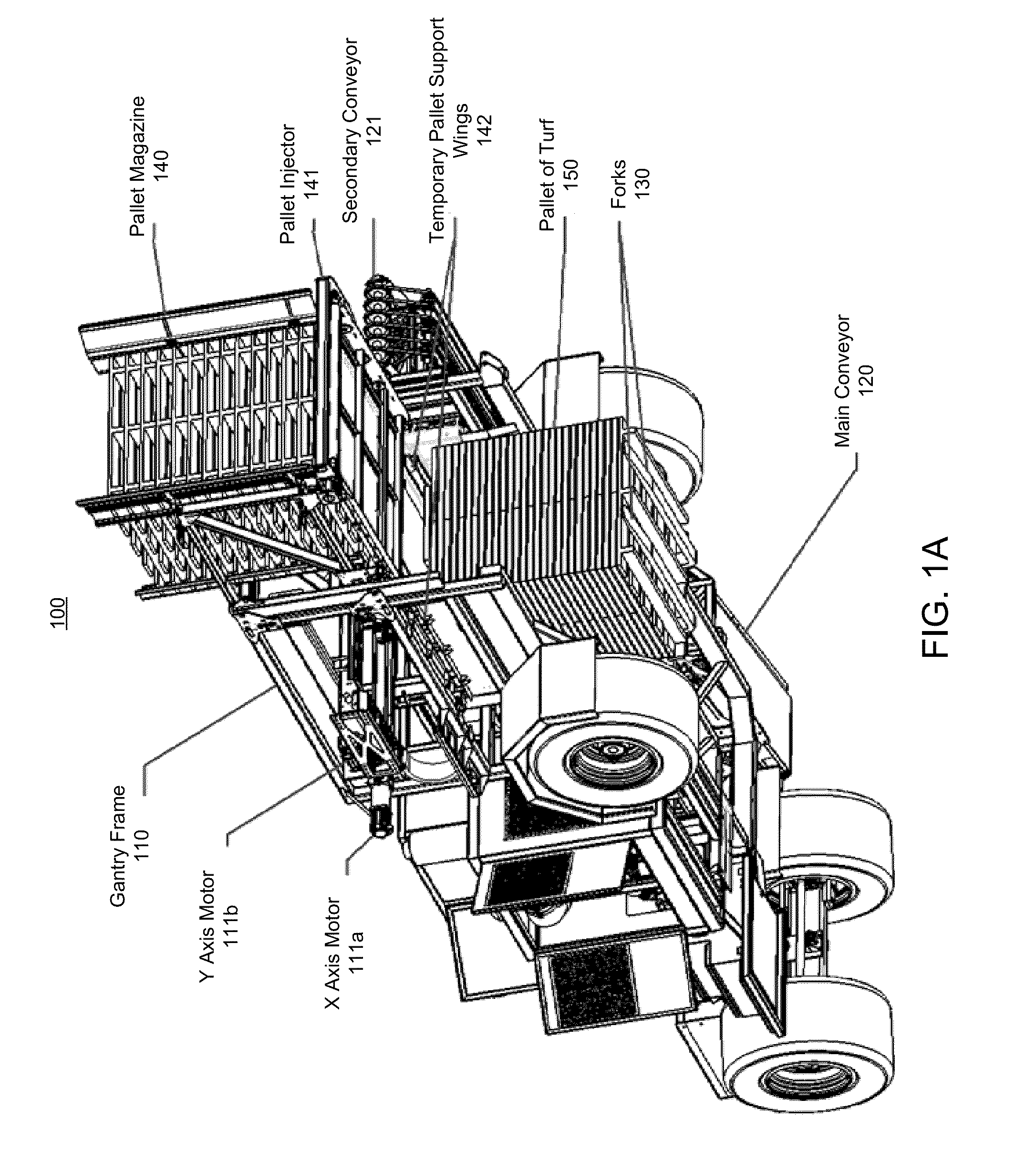
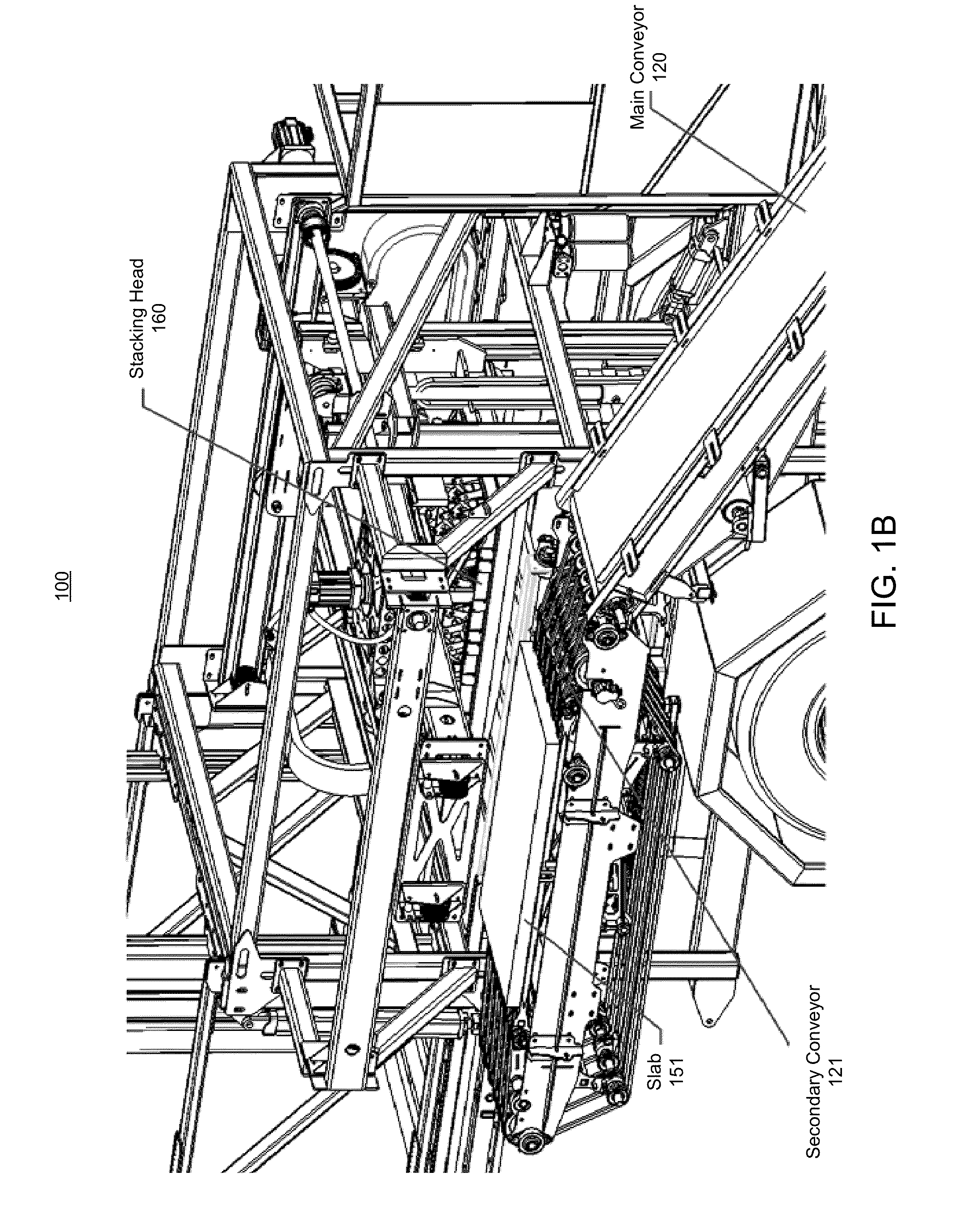
[0028]The present invention extends to a stacking mechanism having electrical actuators for stacking slabs of sod on a sod harvesting machine. The electrical actuators allow the stacking head to be driven in three axes. The stacking mechanism also includes position feedback sensors for reporting the position of the stacking head to enable precision when operating the stacking head at a fast rate. The stacking mechanism of the present invention also provides temporary pallet support wings to enable the continued stacking of slabs of sod on one pallet even while another pallet is being dropped from the sod harvesting machine.

[0029]In some embodiments, the present invention is implemented as an electric actuator based stacking mechanism for a sod harvesting machine. The stacking mechanism includes a supporting mechanism positioned over a conveyor and a pallet support structure. The conveyor is configured to transport slabs of sod into position to be picked up for stacking, and the pall...


PUM


Abstract

The present invention extends to a stacking mechanism having electrical actuators for stacking slabs of sod on a sod harvesting machine. The electrical actuators allow the stacking head to be driven in three axes. The stacking mechanism also includes position feedback sensors for reporting the position of the stacking head to enable precision when operating the stacking head at a fast rate. The stacking mechanism of the present invention also provides temporary pallet support wings to enable the continued stacking of slabs of sod on one pallet even while another pallet is being dropped from the sod harvesting machine.

Description

CROSS-REFERENCE TO RELATED APPLICATIONS[0001]This application claims the benefit of U.S. Provisional Patent Application No. 61 / 619,357, filed Apr. 2, 2012, titled “High Productivity Electrically Operated Turf Stacking System for Automated Turf Harvesting.”BACKGROUND[0002]Turf grass (sod) is a living organism that must be handled properly to ensure its survival when it is removed from one location and transplanted to another. It is cut into slabs that are removed from the field in a serial manner by a harvesting machine which operates continuously. The slabs are cut to a specific transverse width and longitudinal length by a cutting head during the harvesting operation[0003]A conveyor, which may be a chain or belt, carries slabs from the cutting head to a stacking head which picks up and stacks the slabs (e.g. on a pallet). Slabs may be passed to the stacking head flat or in rolls.[0004]When slabs are stacked as rolls, several rolls are accumulated on the conveyor before they are pic...

Claims


Application Information

Patent Timeline
IPC IPC(8): A01B45/04
CPCA01B45/045B65G47/086Y10S414/106B65G47/24G05B19/23A01G20/15
Inventor APOSHIAN, STEVEN R.ASTON, ERIC E.DECKER, WILLIAM M.DRAKE, SAMUEL
Owner FIREFLY AUTOMATIX
Why Eureka
Eureka Blog
Learn More