
Surface-cleaning device and vehicle

a surface cleaning and vehicle technology, applied in waterborne vessels, waterborne equipment, vessel construction, etc., can solve the problems of significant fuel consumption increase, rough surface, and difficulty in developing suitable and practical cleaning equipment for large surfaces such as ships' hulls

Active Publication Date: 2013-10-10
GAC ENVIRONHULL
View PDF2 Cites 28 Cited by
  • Summary
  • Abstract
  • Description
  • Claims
  • Application Information

AI Technical Summary

Benefits of technology

The invention is a device for cleaning surfaces underwater using a rotating disk with nozzles for discharging liquid under pressure. The device includes a housing and a spindle with a rotating disk member supported by the spindle. The disk member has a first side facing the surface to be cleaned and a second side facing away from the surface. The disk member has a plurality of through holes with ridges arranged symmetrically with the rotational axis. The device also includes a pump for supplying liquid to the nozzles and a concave portion on the first side of the disk member. The cleaning device can be connected to a central unit with liquid intake and return openings. The cleaning device also includes a roll axis, pitch axis, and yaw axis, and trimming means for automatically shifting the trimming means' individual centre of gravity when the vehicle is accelerating or changing its orientation in the water. The invention is useful for cleaning surfaces underwater, particularly in the form of an underwater vehicle with a plurality of cleaning devices attached.

Problems solved by technology

A ship's hull which is subjected to marine organisms is prone to barnacle growth and general fouling, making the hull surface rough and uneven.
This leads to greater friction resistance when the ship is propelled through the water, which in turn means a significant increase in fuel consumption.
Developing suitable and practical cleaning equipment for large surfaces, such as ships' hulls, is a considerable challenge, partly due to the hulls' limited accessibility when submerged in water.
Also, ships' hulls are commonly coated with toxic paints, containing organic tin compounds.
Such compounds should not be dislodged from the hull, as they may contaminate the surrounding marine life.

Method used


Image

  • Surface-cleaning device and vehicle
  • Surface-cleaning device and vehicle
  • Surface-cleaning device and vehicle

Examples


Embodiment Construction

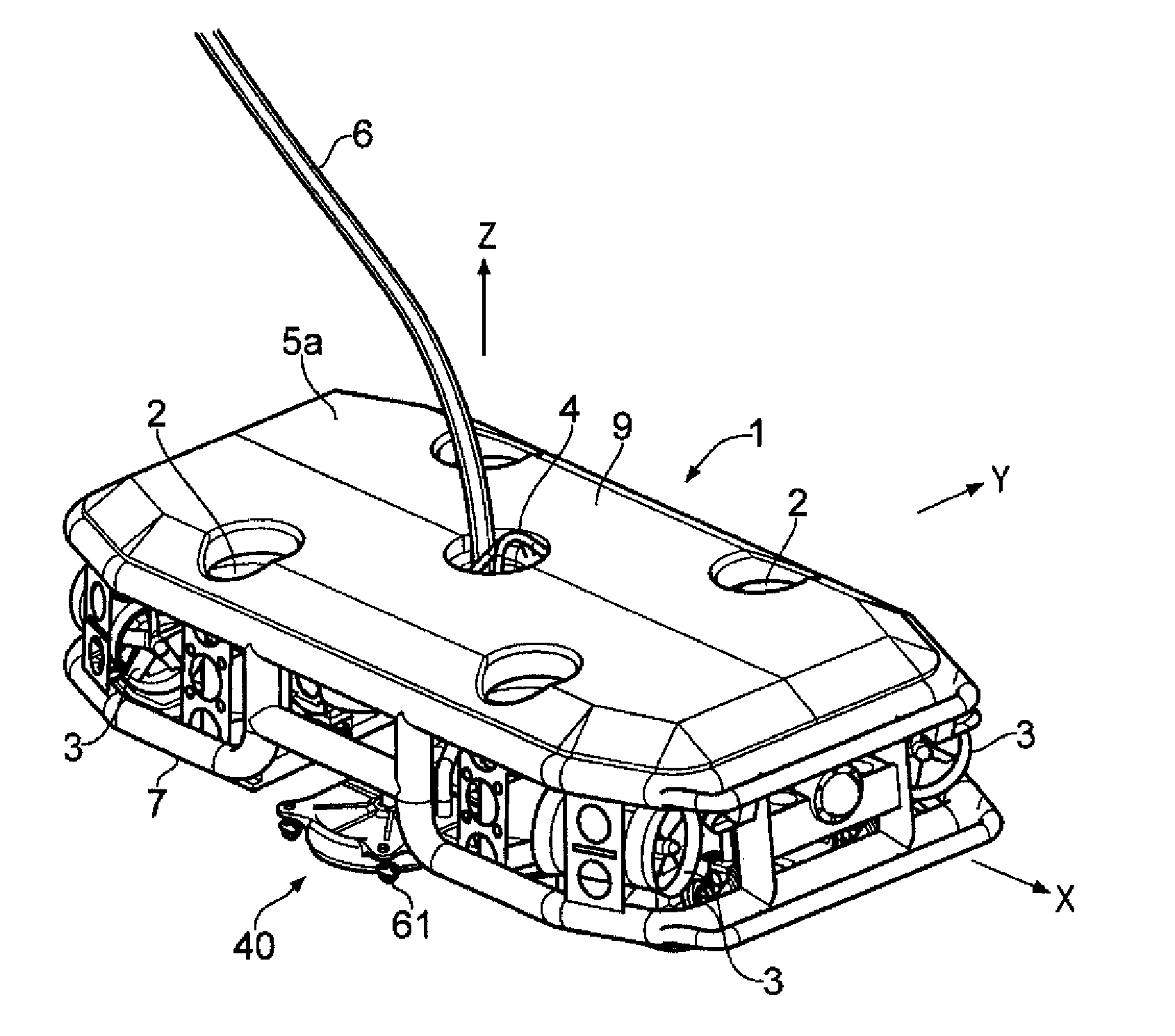
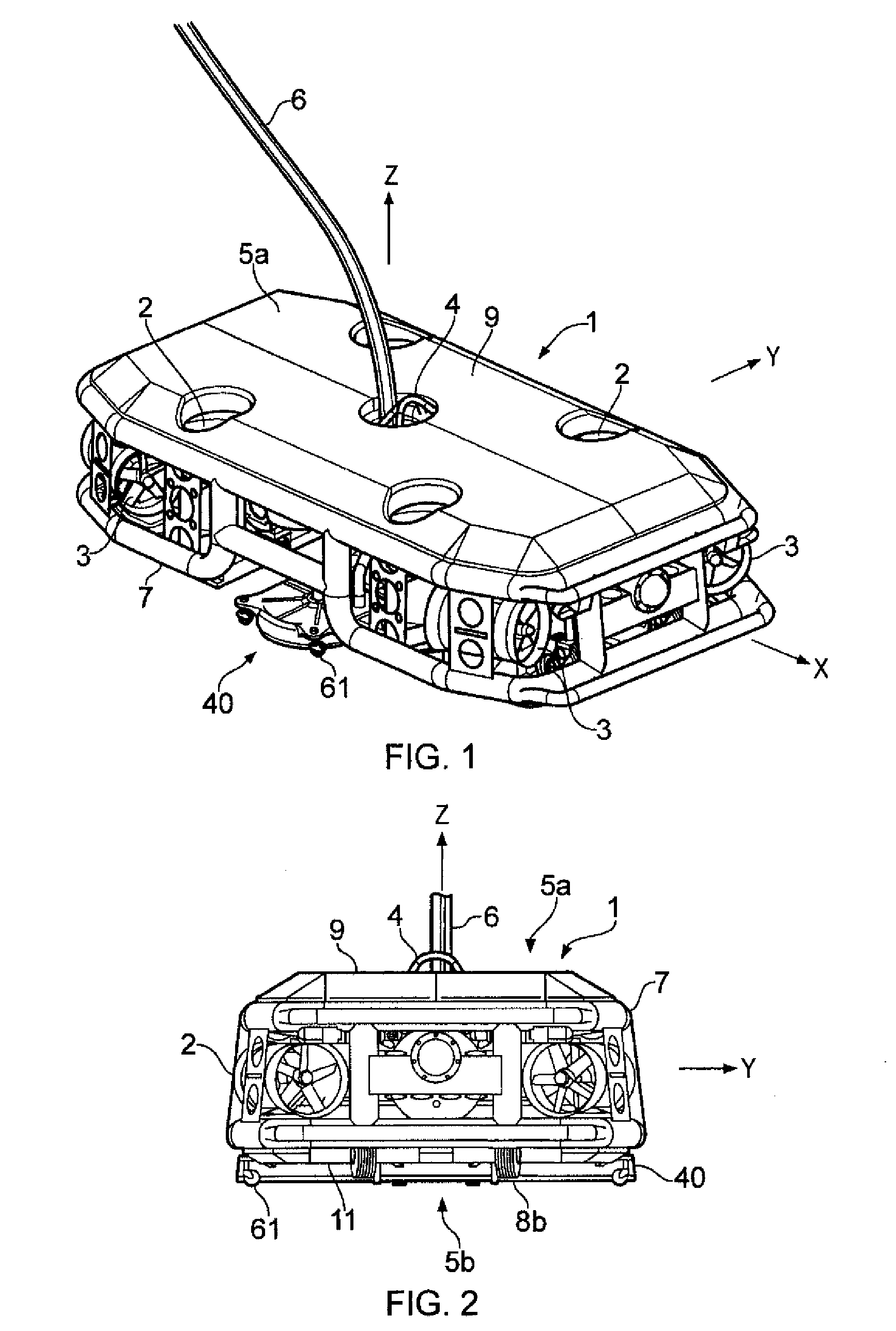
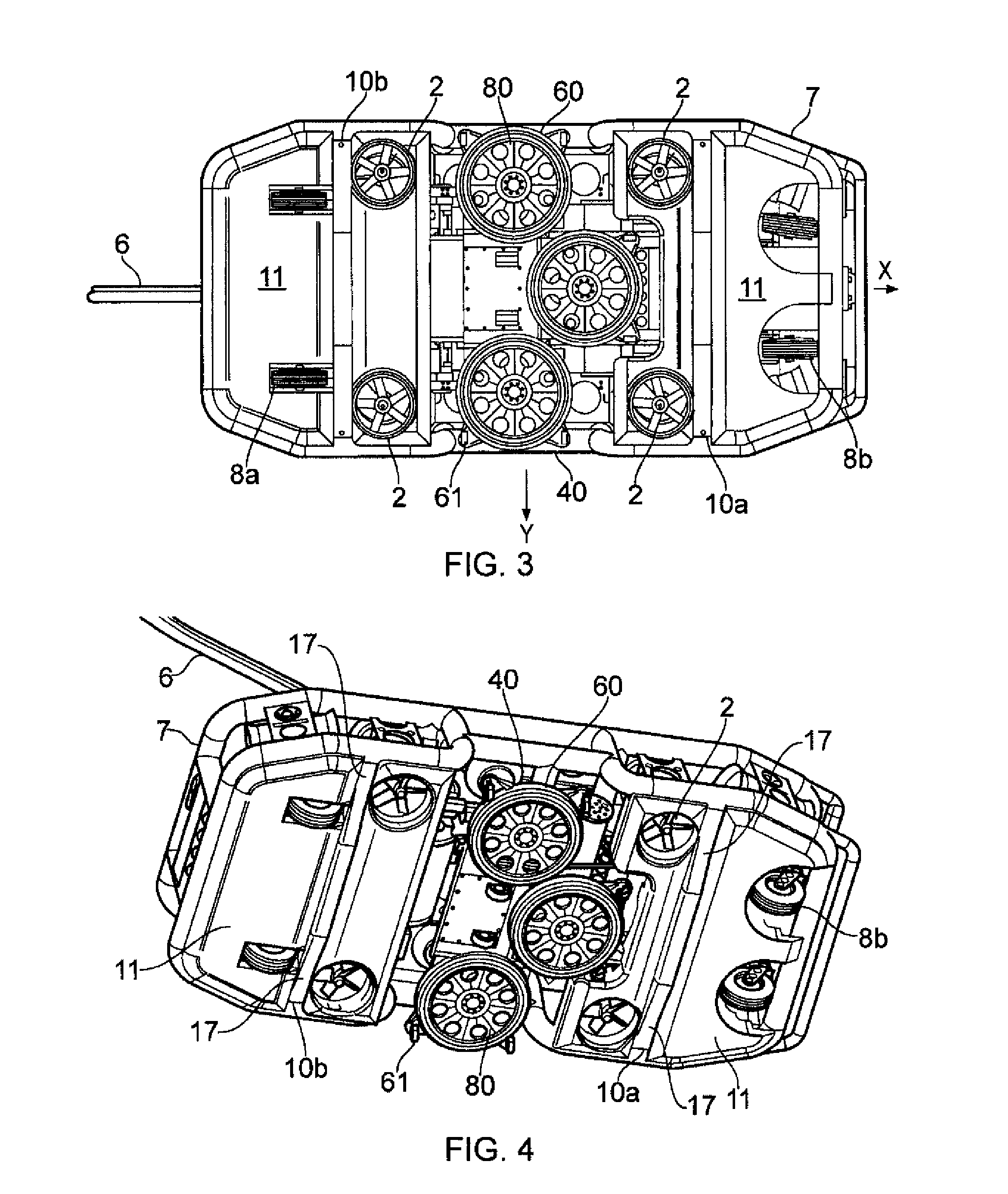
[0051]Referring initially to FIG. 1 and FIG. 2, the cleaning robot 1 in the illustrated embodiment basically comprises a tubular frame 7 carrying a cleaning apparatus 40. The cleaning robot 1 is a neutrally buoyant ROV being remotely controlled by an umbilical 6. The umbilical 6 holds power cables and control cables and extend to power and control units (not shown), located for example on a ship or barge on the water surface. The umbilical 6 also holds power and control cables, as well as liquid supply and return hoses, for operation of the cleaning apparatus 40.

[0052]A coordinate system has been defined for the ROV 1, the axes of which intersect the ROV's centre of gravity (CG; see also FIGS. 20 and 21), and where the x axis defines a roll axis; the y axis defines a pitch axis; and the z axis defined a yaw axis. When floating in the water in the state shown in FIGS. 1 and 2, the z axis points upwards and the ROV has an upper side 5a, to which the umbilical 6 and a lifting padeye 4 ...


PUM


Abstract

A remotely operated underwater vehicle for cleaning surfaces submerged in water, the underwater vehicle having a first side, a second side, a propulsion means, a plurality of trimming means, a first buoyancy means attached to the first side and a second buoyancy means attached to the second side. Elements of the plurality of trimming means are arranged on opposite sides of the centre of gravity of the vehicle and at least one of the plurality of trimming means has a movable mass and a displacement region into which the movable mass can move. The centre of gravity of the vehicle is automatically shifted when the vehicle is accelerating or changes orientation, in which the first buoyancy means provides more buoyancy than the second buoyancy means such that the centre of buoyancy is located above the centre of gravity of the vehicle irrespective of the orientation of the vehicle.

Description

FIELD OF THE INVENTION[0001]The invention concerns surface-cleaning devices. More specifically, the invention concerns the cleaning of large submerged surfaces which offer limited availability for conventional cleaning methods, such as a partly submerged hull of a ship. The invention also concerns a remotely operated underwater vehicle for carrying the cleaning devices.BACKGROUND OF THE INVENTION[0002]A ship's hull which is subjected to marine organisms is prone to barnacle growth and general fouling, making the hull surface rough and uneven. This leads to greater friction resistance when the ship is propelled through the water, which in turn means a significant increase in fuel consumption. It is known that a 1% increase in friction causes approximately a 3% fuel consumption increase. Frequent hull cleaning is therefore required, both from economical and environmental points of view.[0003]Developing suitable and practical cleaning equipment for large surfaces, such as ships' hulls,...

Claims


Application Information

Patent Timeline
IPC IPC(8): B63B59/08
CPCB63B59/08B63G8/26B63G8/001
Inventor ANDERSEN, ROBERT
Owner GAC ENVIRONHULL
Learn More