Power supply control system and device

a power supply control and power supply technology, applied in the direction of electric variable regulation, process and machine control, instruments, etc., can solve the problems of energy saving globes of both transformers, early failure, etc., and achieve the effect of improving power factor and vastly superior step respons

Inactive Publication Date: 2013-10-10
INDICE SEMICON INC
View PDF2 Cites 15 Cited by
  • Summary
  • Abstract
  • Description
  • Claims
  • Application Information

AI Technical Summary

Benefits of technology

[0017]The hardware approach can include using logical switching gates. This allows primitive decision making to occur at speeds faster than normal such as in the megahertz or gigahertz, using cheap available hardware
[0024]The power control can include en active rectifier of input power to guarantee FET gate is within threshold in which there is a FET controller in combination with a linear regulator. The linear regulator can incorporate a large Resistor and large Zener voltage so as to minimise power losses through minimising current in control switching. Control can be analogous to AND or NAND gates.
[0026]In this way operation of FETs with voltages of less than 1 Volt are still controlled by the rectifier. This also avoids punch through as operation of a pair of MOSFETs cannot occur at the same time.
[0028]There is continuous current mode inductor—virtually no input capacitance. Simultaneous regulation of high and low speed parameters (e.g. bad current, voltage, temperature, etc). No electrolytic capacitance is necessary due to high speed, ceramic based design (cheap, incredibly long life, compact)
[0029]It provides a vastly superior step response due to single cycle control.
[0030]EMC is easier due to low, asynchronous ripple. Further the power factor is improved due to virtually no input capacitance.

Problems solved by technology

However inrush currents can exceed 15 Amps when inverters first start, stalling oscillation and damaging rectifiers, causing early failure in both transformers energy saving globes.

Method used


Image

  • Power supply control system and device
  • Power supply control system and device
  • Power supply control system and device

Examples


Embodiment Construction

[0058]The invention with reference to the drawings shows a power supply control system and its components comprising a switching-mode power supply with cycle by cycle, asynchronous control scheme, the control scheme using logical switching means, wherein the control is for managing the power source to match the required load as well as determining the regulation of the load.

[0059]The invention provides a switching-mode power supply with cycle by cycle, asynchronous control scheme. This makes use of simulated electronic logic gates that are provided in hardware. However to determine the electronic simulation and to make use of a mixing of instant and average signals through a feedback system is necessary to assimilate and artificial intelligence neural control network such as a perceptron.

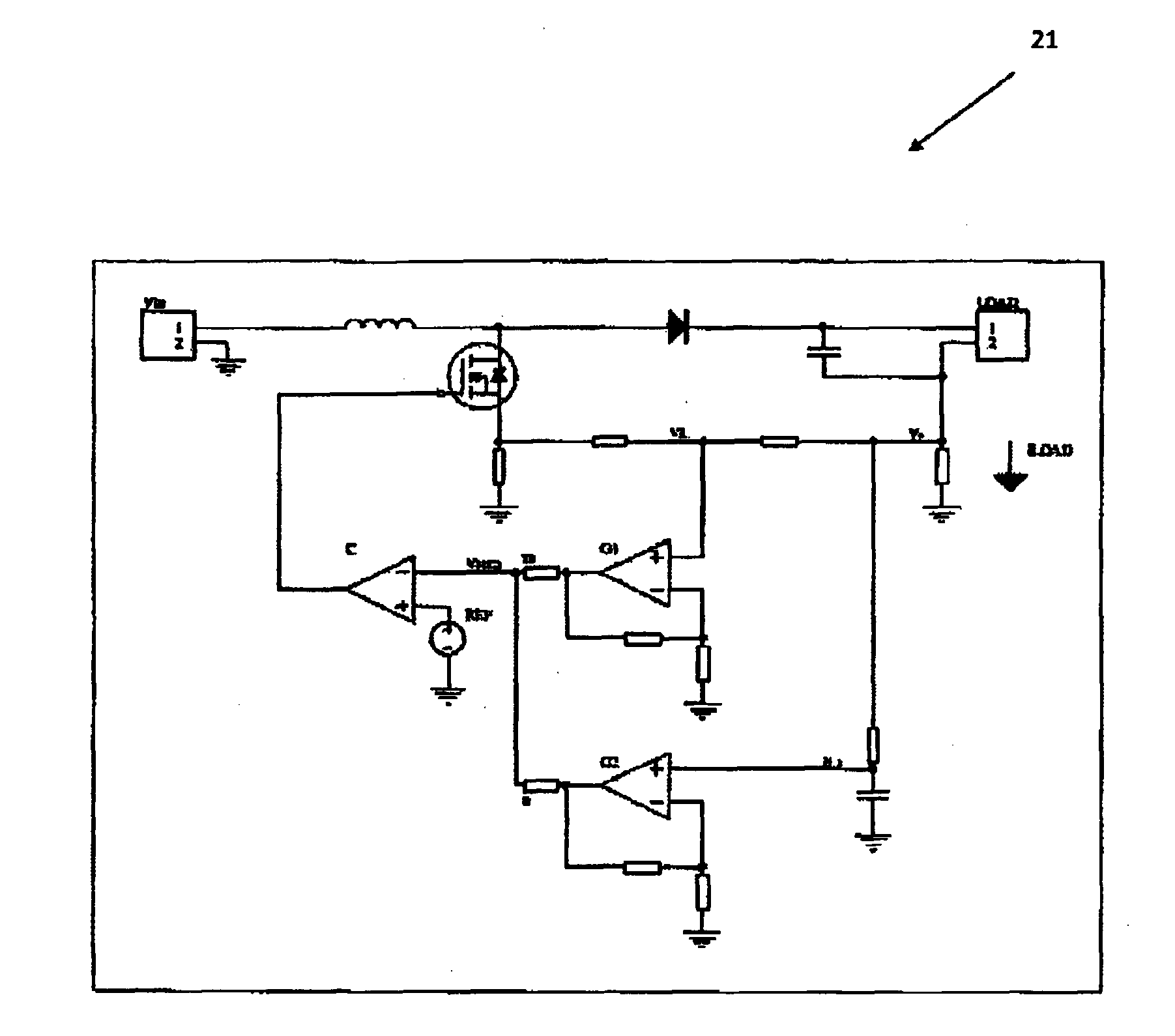
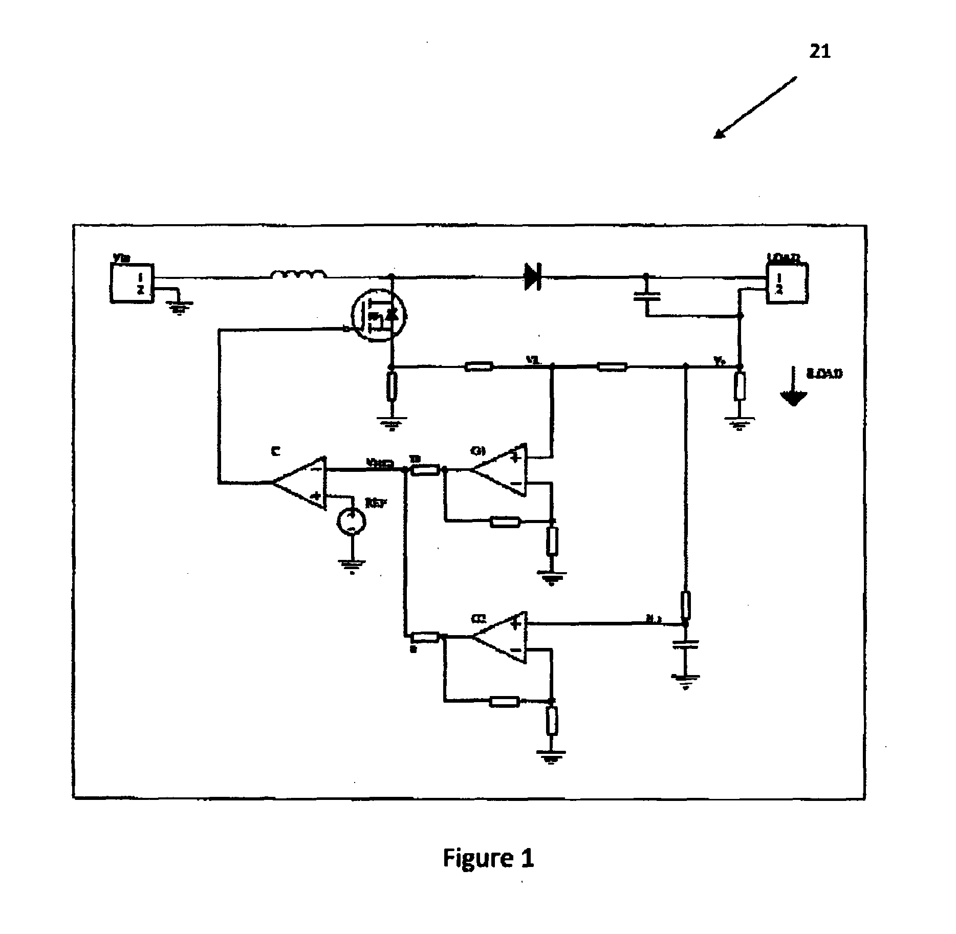
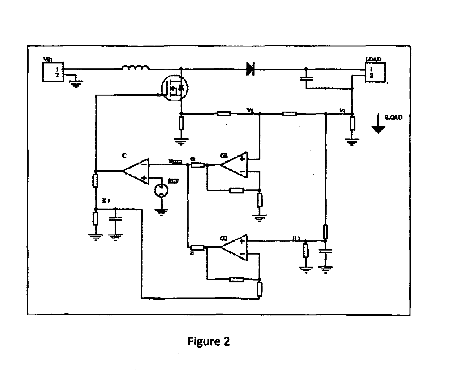
[0060]Referring to FIGS. 1 to 4 there are four aspects of the switching-mode power supply with cycle by cycle, asynchronous control scheme of the invention.

[0061]FIG. 1 is a circuit diagram of a sim...


PUM


Abstract

Power supply control system for a switching-mode power supply with cycle by cycle, asynchronous control scheme, making use of simulated electronic logic gates for the logical switching means and further including assimilation and artificial intelligence neural control network, such as a perceptron, to determine the electronic simulation and to make use of a mixing of instant and average signals through a feedback system.

Description

FIELD OF THE INVENTION[0001]The present invention relates to a power supply control system and device using single cycle control for power sources such as for lights, and more particularly, to switch mode power supplies (SMP8) but not limited to such.BACKGROUND TO THE INVENTION[0002]A power supply often has en inverter or converter device for the conversion of available power of one set of characteristics to another set of characteristics to meet specified requirements. It can therefore be a circuit that provides power with the characteristics required by the load from a mains supply power source. For example a mains supply power source might be the 50 Hertz, single phase, 240 Volt AC power found in Australia but the load can be a circuit in a personal computer that requires regulated 5V DC power. Alternatively the load could be a 20 Watt Halogen light supply. The power supply therefore requires a circuit that makes the 240 V AC power source and 5 V DC load compatible.[0003]A switch...

Claims


Application Information

Patent Timeline
Patent Type & Authority Applications(United States)
IPC IPC(8): H02M3/156H05B33/08H05B44/00
CPCH05B33/0815H02M3/157H02M3/156H05B45/38H05B45/375H05B45/385Y02B20/30
Inventor HAMOND, JAMES
Owner INDICE SEMICON INC
Why Eureka
Try Eureka