
Power control

a power control and power technology, applied in the direction of efficient power electronics conversion, amplifiers with semiconductor devices/discharge tubes, and use of semiconductor lamps, can solve the problems of power loss, power amplifiers incur a number of power losses, and power loss in a variety of ways, so as to limit power usage and power losses.

Inactive Publication Date: 2014-10-23
INDICE SEMICON INC
View PDF5 Cites 9 Cited by
  • Summary
  • Abstract
  • Description
  • Claims
  • Application Information

AI Technical Summary

Benefits of technology

The patent describes a method for controlling power in electronic circuits. It uses a combination of a FET controller and a linear regulator to minimize power losses and ensure the FETs are always within a safe operating range. The method also includes a state switching in regulation that compensates for power usage and losses to achieve efficient and precise control over a large range of input voltages. Overall, the method allows for real-time, cycle by cycle digital control with design flexibility and advantages.

Problems solved by technology

Important concerns in power control circuits are power loss and power storage.
In switch-mode power supplies, power loss occurs in a variety of ways.
However such a power amplifier incurs a number of power losses.

Method used


Image

  • Power control
  • Power control
  • Power control

Examples


Embodiment Construction

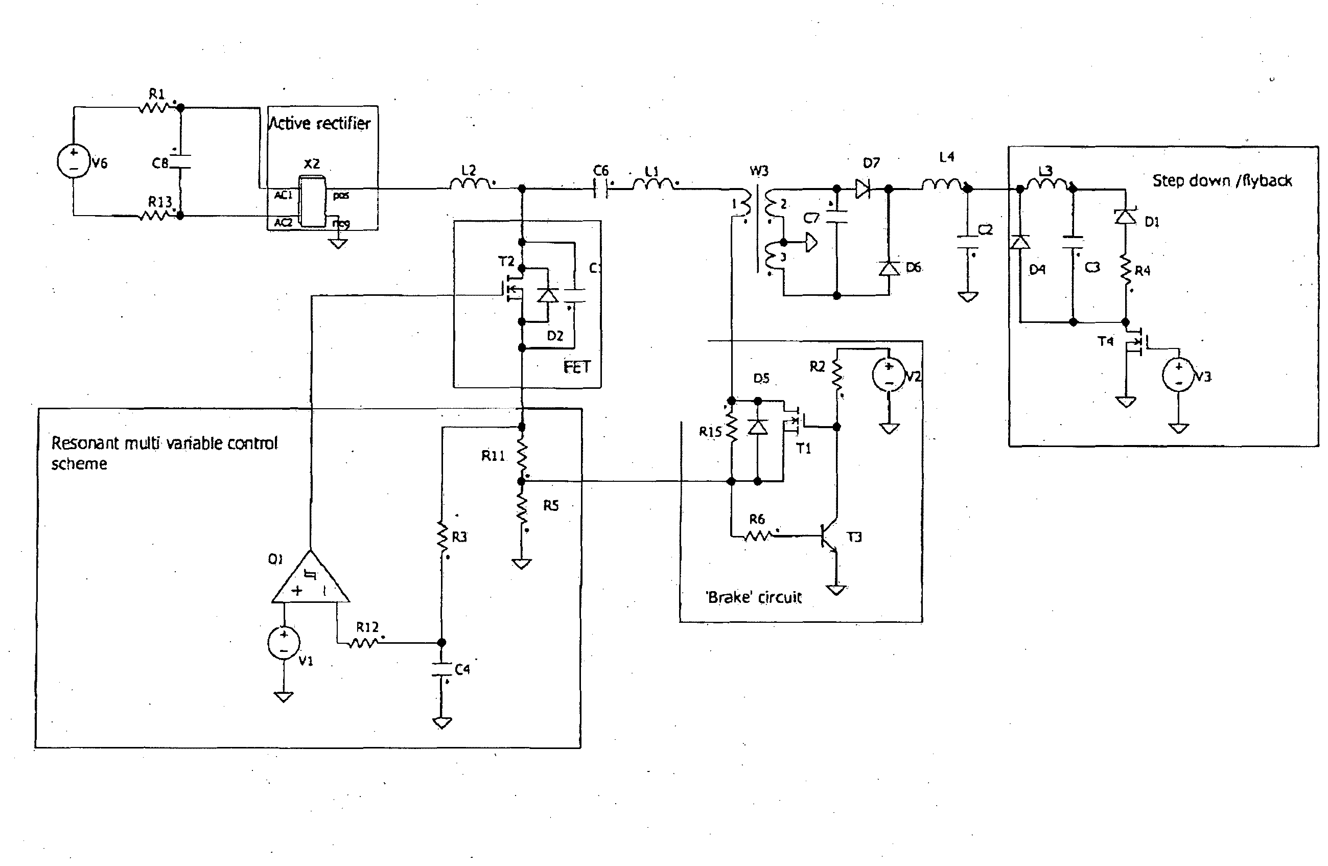
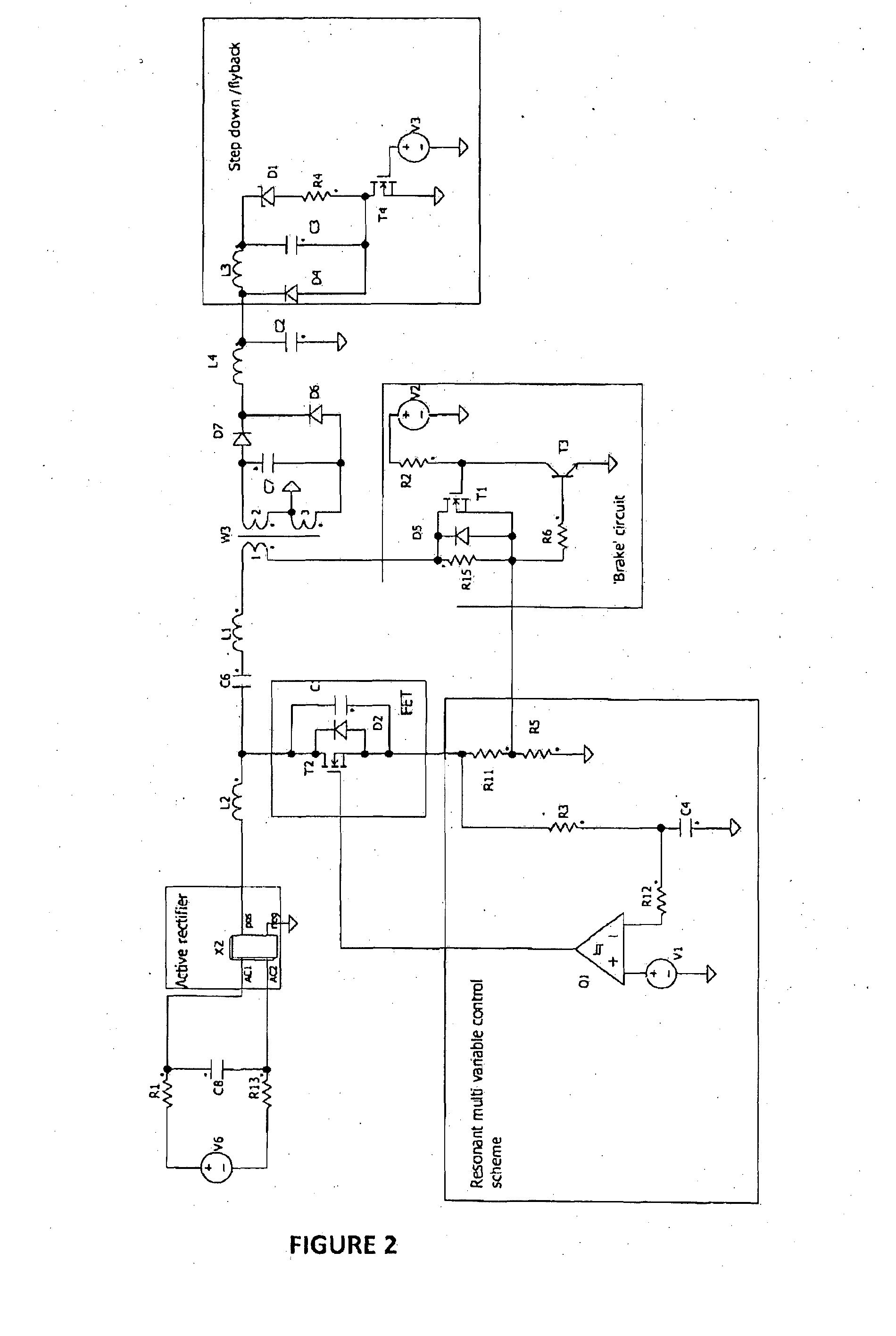
[0045]With reference to the drawings in this preferred embodiment, as shown in FIG. 2 the invention provides an E class amplifier having all sections of[0046]A. Resonance tracking[0047]B. Brake Circuit[0048]C. Rectifier[0049]D. Step Down / Fly Back

A. Resonance Tracking

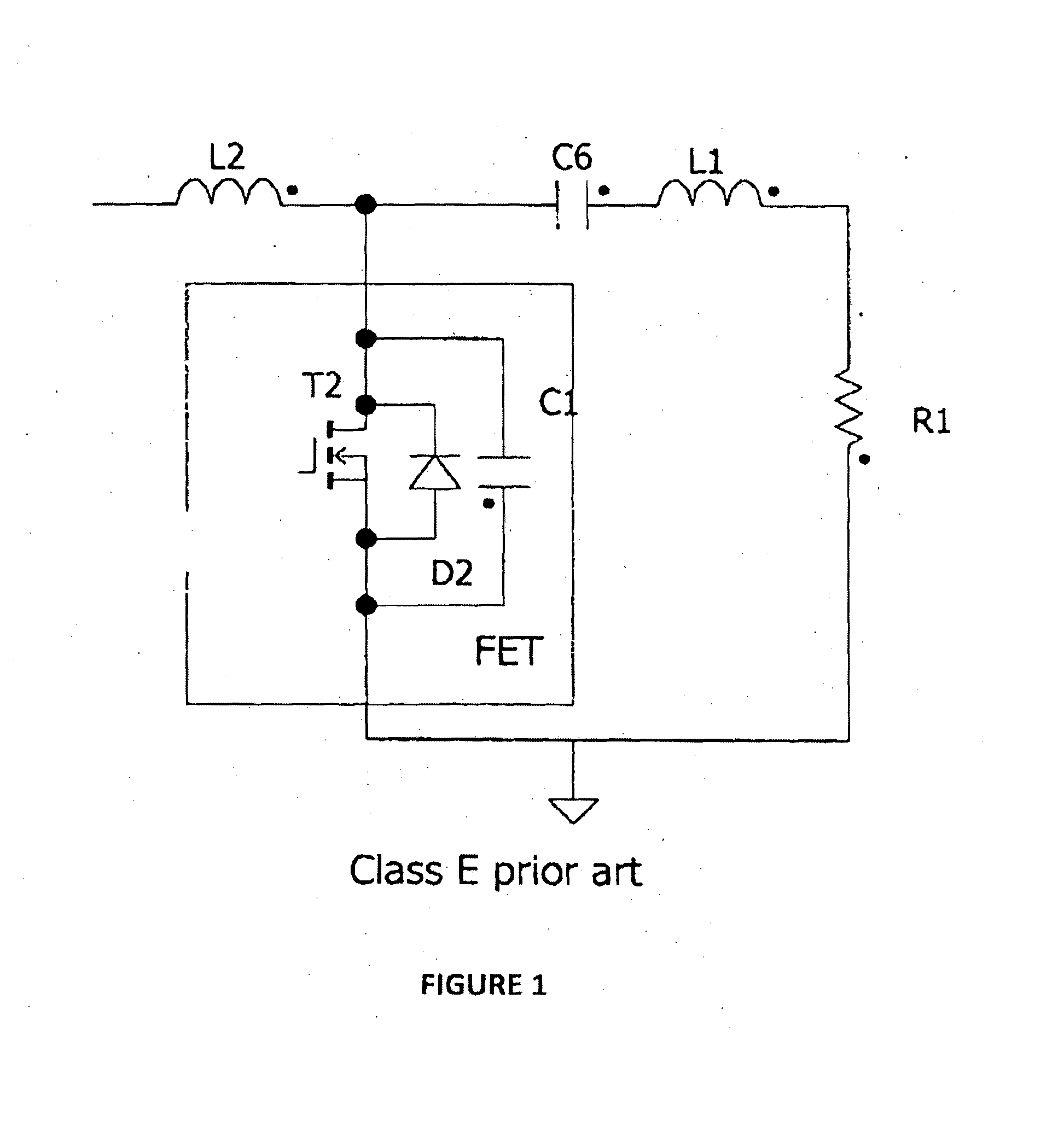
[0050]As shown in FIG. 1 one particular form of power control is the class E amplifier. A standard Class E amplifier has a FET with a transistor (T2) connected via a serial “LC” circuit to the load (R1), and is connected to the supply voltage (not shown) via a large inductor (L2), which acts as a rough constant current source.

[0051]However expanding this to an AC application, either low or high voltage, is shown in FIG. 3. Here is the inclusion of the new resonant controller with components 01, V1 (reference voltage), R2 (resonance sensor) and R5 (input current sensor).

[0052]The power control for an AC application includes resonance tracking system of an input inductor being fed by a power source wherein the resonance tr...


PUM


Abstract

A Class E amplifier having a FET with a transistor (T2) connected via a serial “LC” circuit to the load, and connected to a supply voltage via a constant current source, the amplifier further including a resonant controller, wherein the resonant controller provides power control for an AC application and includes resonance tracking system of an input inductor being fed by a power source with the resonance tracking system using a resistor resonance detector having two sense resistor loads in series.

Description

FIELD OF THE INVENTION[0001]This invention relates to power control and in particular to distinct control of switching to achieve power control. Even more particular the invention provides improved means of power control in silicon topologies but is not limited to such.[0002]Whilst the invention may be applied to a range of power sources from low voltage to mains voltage and for Direct Current or Alternating Current (DC or AC), for convenience sake it shall be described herein in terms of a control of Light Emitting Diodes (LEDs) for a range of voltages. In particular it will be described with regard to a class E amplifier. However the scope of the invention is not limited thereto and can include one or more of the sections for other power control uses.BACKGROUND TO THE INVENTION[0003]Important concerns in power control circuits are power loss and power storage. In switch-mode power supplies, power loss occurs in a variety of ways. Some of the dominant methods are:[0004]1. Ohmic pow...

Claims


Application Information

Patent Timeline
Patent Type & Authority Applications(United States)
IPC IPC(8): H03F3/217
CPCH03F3/2176H02M3/335H05B45/375H05B45/385H02M1/0003Y02B20/30Y02B70/10H02M1/0058
Inventor HAMOND, JAMES
Owner INDICE SEMICON INC
Learn More