Antenna Arrangement
- Summary
- Abstract
- Description
- Claims
- Application Information
AI Technical Summary
Benefits of technology
Problems solved by technology
Method used
Image
Examples
first embodiment
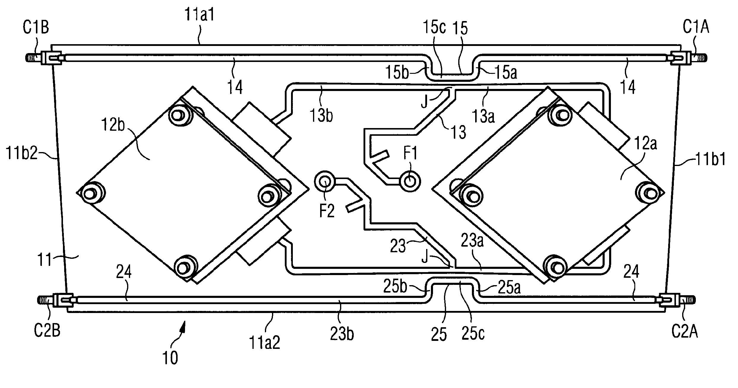
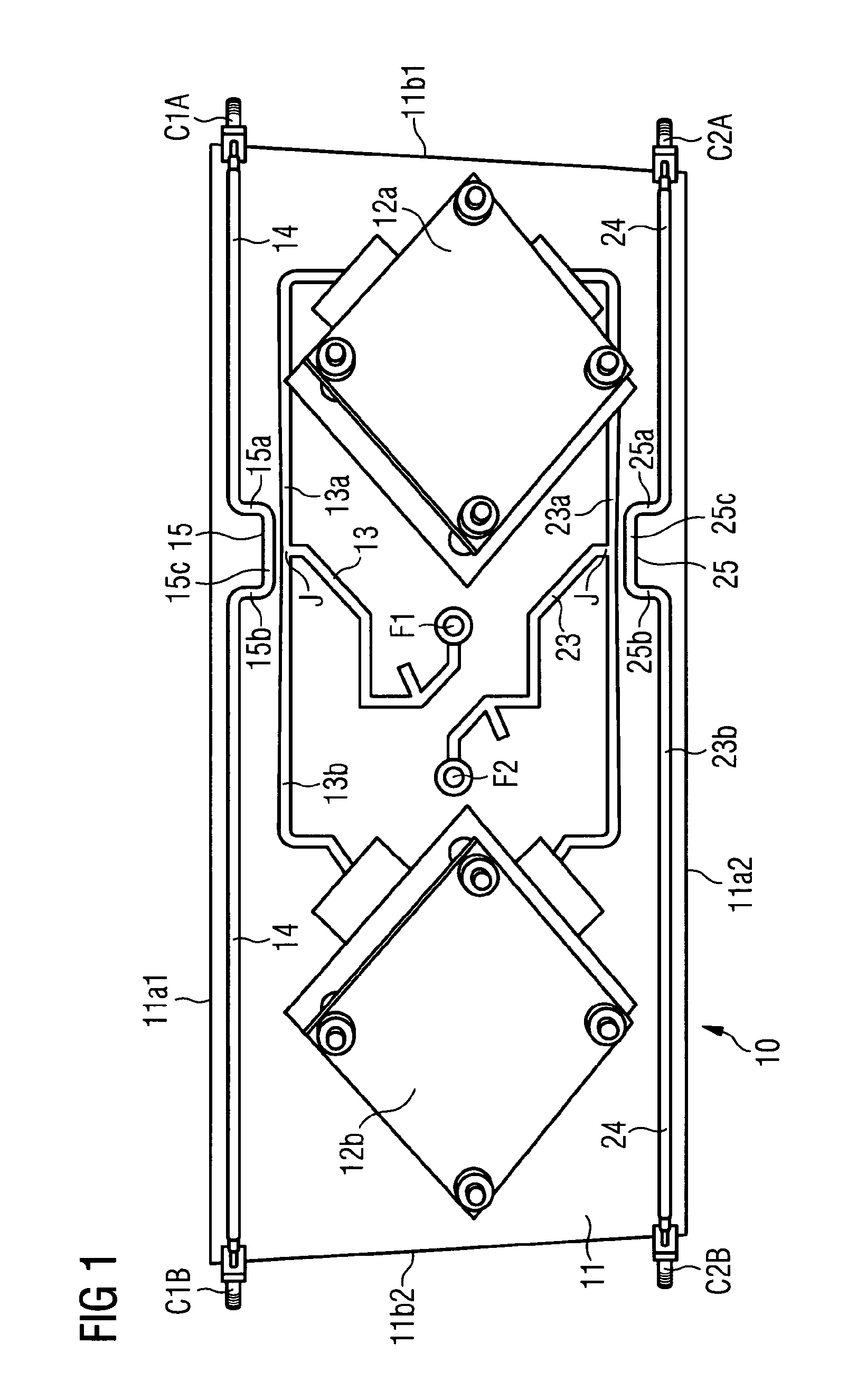
[0052]The layout of the transceiver ports TRX1-TRXn, feeder line 33 and antenna elements AE1-AEn is the same as that of the feeder ports F1, F2, feeder line 13, 23 and antenna elements 12, 22 described above. However, the difference between this embodiment and the previous embodiment is that only one calibration line 34 is provided, which is connected between the resistor R and the calibration radio CR in the antenna array A. The calibration line 34 runs substantially down the centre of the base on which the antenna elements AE1-AEn are mounted between each pair of transceiver ports TRX1, TRX2 TRXn-1, TRXn.
[0053]No inductive coupler as such is provided in the calibration line 34. However the calibration line 34 is arranged in close proximity to the junction of where each feeder line 33 splits into branches leading to each of the antenna elements of the pair. This means that signals fed between each feeder line 33 and the antenna element AE1-AEn can be inductively coupled over air b...
second embodiment
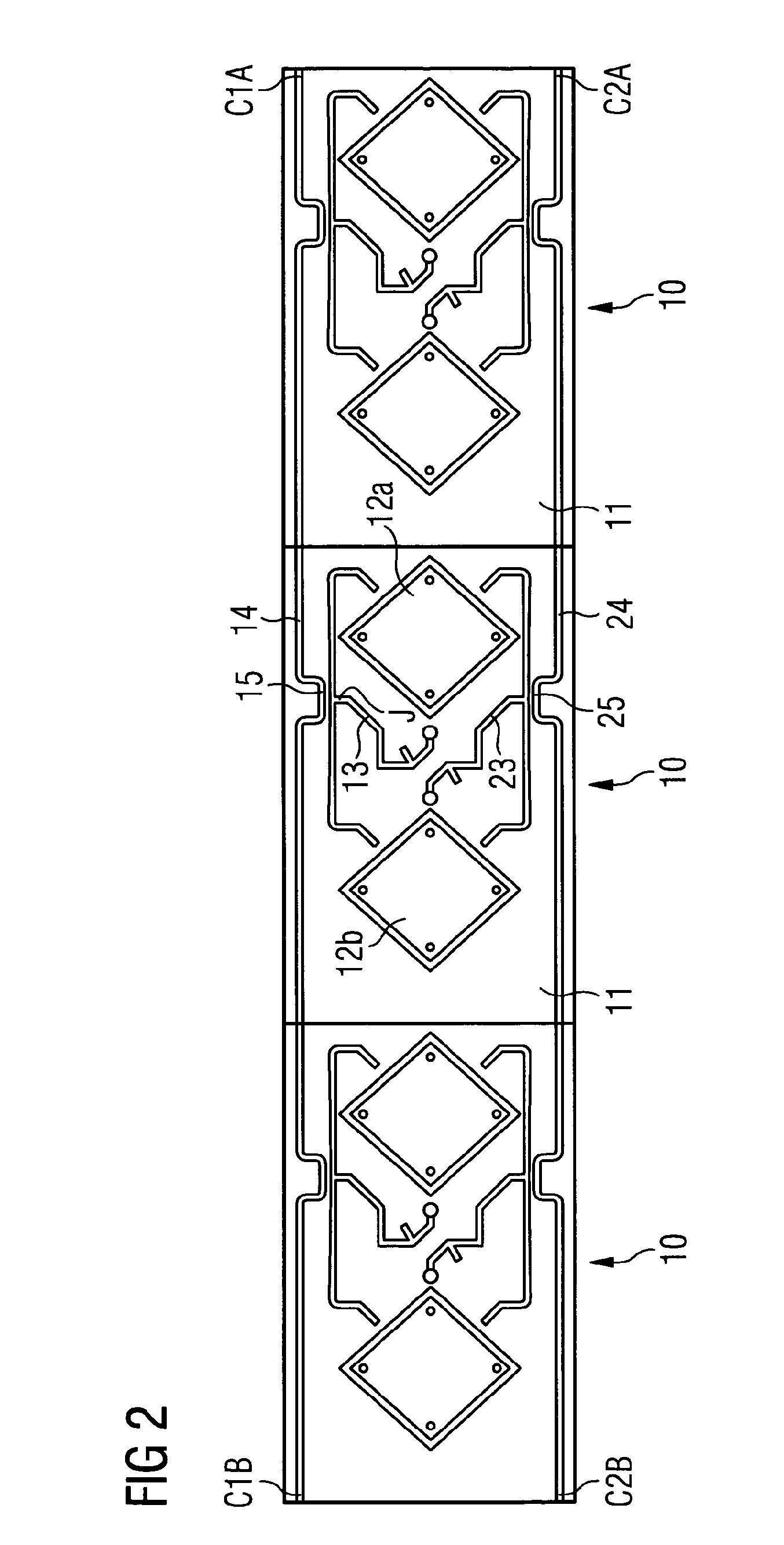
[0054]FIG. 4 shows several antenna arrays A coupled together between two calibration radios CR1 and CR2 so that they are cascaded in both rows and columns.
[0055]This arrangement is effectively an infinite matched / terminated coupler line coupling signals to and from the calibration line 34 and 1-n number of antenna elements AE1-AEn. If the calibration line 34 is arranged equidistant from the transceiver ports in each transceiver port pair, this means that signals will couple equally to and from the calibration radios CR1 and CR2. However, the calibration line may also be arranged on one side of the base, instead of centrally, in which case any asymmetrical coupling to CR1 and CR2 can be compensated for in calibration algorithms.
third embodiment
[0056]FIG. 5 shows a third embodiment having a simplified arrangement in which an antenna arrangement 40 has only one antenna element 42, instead of two. RF signals are fed to the antenna element 42 from a feeder port F4 via a feeder line 41 connecting the feeder port F4 and the antenna element 42. In this embodiment a calibration line 44 is arranged proximal to and spaced apart from the feeder line 41 in the same plane as the feeder line 41. The feeder line 41 has just one branch, at least a section of which is parallel to the calibration line. The calibration line 44 may be coupled to the calibration line 44 of other antenna arrangements using a commercial RF coupling line. Alternatively, the antenna element 42, feeder line 41 and calibration line 44 may be mounted on a printed circuit board having connector ports for connecting to corresponding connector ports on other antenna elements. In either configuration, the antenna arrangements may be connected together so that they are c...
PUM
 Abstract
Description
Claims
Application Information
 - R&D
- Intellectual Property
- Life Sciences
- Materials
- Tech Scout
- Unparalleled Data Quality
- Higher Quality Content
- 60% Fewer Hallucinations
Browse by: Latest US Patents, China's latest patents, Technical Efficacy Thesaurus, Application Domain, Technology Topic, Popular Technical Reports.
© 2025 PatSnap. All rights reserved.Legal|Privacy policy|Modern Slavery Act Transparency Statement|Sitemap|About US| Contact US: help@patsnap.com


