Accurate Telescope Tracking System with a Calibrated Rotary Encoder

a technology of rotary encoder and telescope tracking system, which is applied in the field of accurate telescope tracking system with rotary encoder, can solve the problems of inaccurate tracking of objects being imaged, inaccurate correction, and more expensive encoder, and achieve less accurate, more expensive encoder, and higher accuracy

Inactive Publication Date: 2013-10-10
BATCHVAROV ANDREY BORISSOV
View PDF0 Cites 16 Cited by
  • Summary
  • Abstract
  • Description
  • Claims
  • Application Information

AI Technical Summary

Benefits of technology

[0004]The present invention utilizes an incremental quadrature optical encoder with measuring relative rotation to the initial orientation at the start of imaging using the pulses generated by the encoder. Provided that the encoder pulses are exactly equally spaced in rotation units, the actual rotation can be calculated from the pulse count. If this rotation is different from the expected one, then a correction signal can be sent to the telescope RA drive system. Frequency at which the correction needs to be made depends on the quality of the particular telescope RA drive system and for widely used amateur telescopes is between 1 and 4 seconds. Since one rotation of the Earth is about 86,000 seconds, an encoder with at least 20,000 counts per revolution (CPR) must be used. Any inaccuracy of the actual position of pulses from the encoder will result in wrong corrections and inaccurate tracking of the object being imaged. Higher accuracy demands more a

Problems solved by technology

Any inaccuracy of the actual position of pulses from the encoder will result in wrong corrections and inaccurate tracking of the objec

Method used


Image

  • Accurate Telescope Tracking System with a Calibrated Rotary Encoder
  • Accurate Telescope Tracking System with a Calibrated Rotary Encoder
  • Accurate Telescope Tracking System with a Calibrated Rotary Encoder

Examples


Embodiment Construction

[0020]All illustrations of the drawings are for the purpose of describing selected versions of the present invention and are not intended to limit the scope of the present invention.

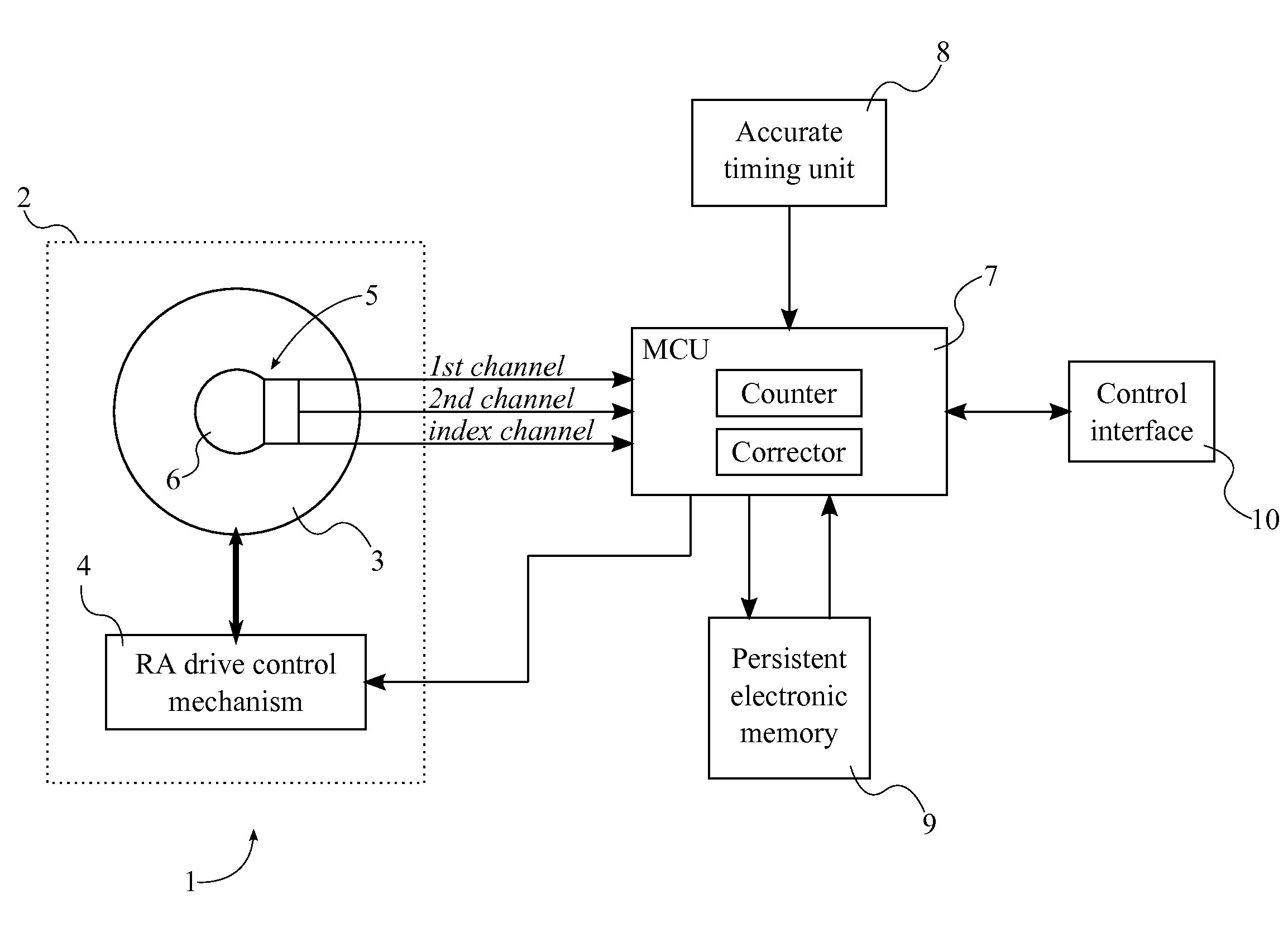
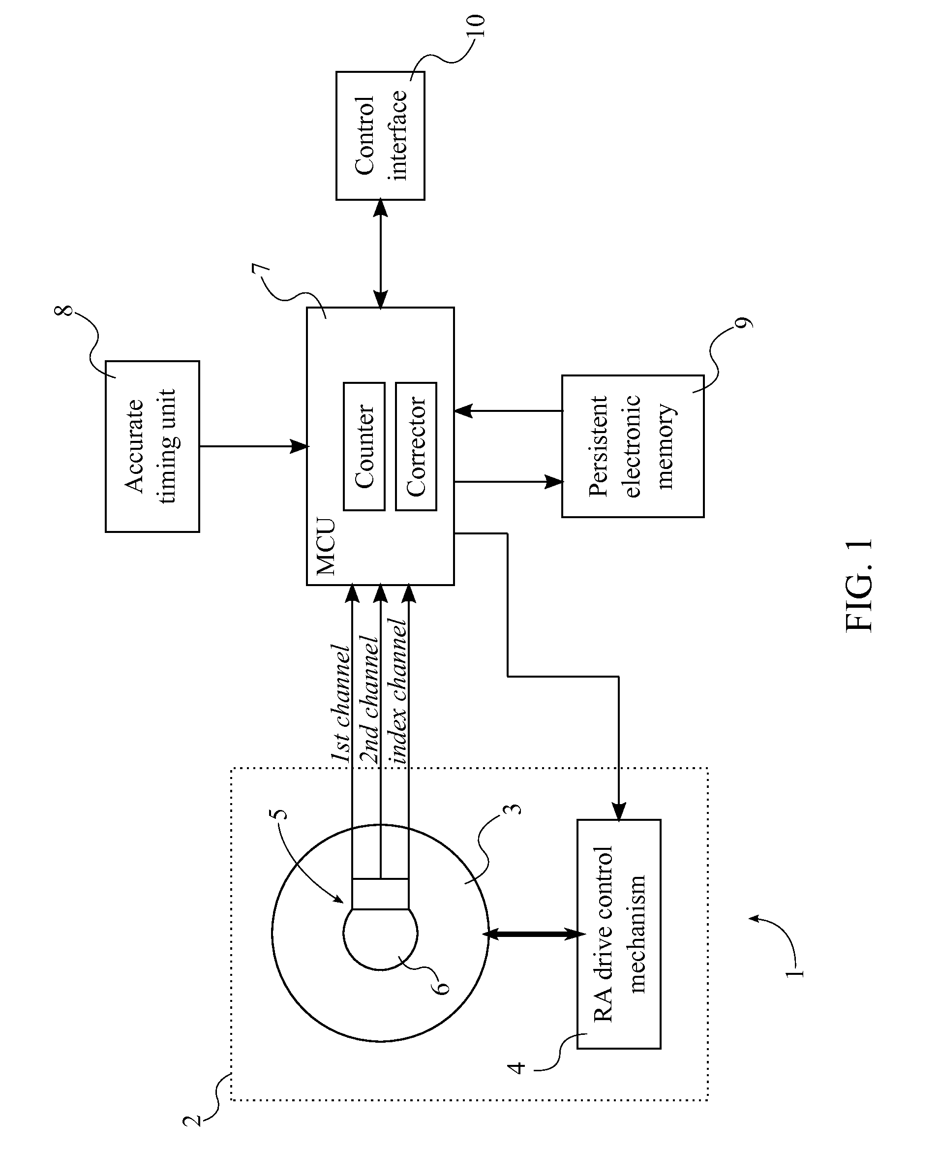
[0021]The present invention is a system and a method to improve the Right-Ascension-rotation accuracy for a telescope. As can be seen in FIG. 1, the system mainly comprises a telescope mount 1, an incremental quadrature optical (IQO) encoder 5, a microcontroller unit (MCU) 7, an accurate timing unit 8, a persistent electronic memory 9, and a control interface 10. The telescope mount 1 is the means to support and rotate a telescope and comprises a Right Accession (RA) drive system 2, which allows the telescope to rotate in the Right Accession arc. The RA drive system 2 comprises an RA drive shaft 3 and an RA drive control mechanism 4. The telescope mount 1 rotates about the RA drive shaft 3, and the RA drive control mechanism 4 manages the rotation of the RA drive shaft 3. The IQO encoder 5 is used to det...


PUM


Abstract

A system with a calibrated rotary encoder can be used for accurate telescope tracking along the Right Ascension (RA) rotation axis. The system includes an incremental quadrature optical encoder, a microcontroller unit (MCU), a timer, an electronic memory, and a control interface. The rotor of the encoder is coaxially attached to the RA drive shaft of the telescope mount in order to send angular position data for the RA drive shaft to the MCU. The MCU evaluates the angular position data for errors and send corrections to the control mechanism of the RA drive shaft. The electronic memory stores calibrated reference data, which is compared to the angular position data by the MCU. The calibrated reference data can be found by measuring the movement of a reference star across an image. The system can also calculate an accurate visible speed for the Earth's rotation in a desired direction.

Description

[0001]The current application claims a priority to the U.S. Provisional Patent application Ser. No. 61 / 621,848 filed on Apr. 9, 2012.FIELD OF THE INVENTION[0002]The present invention relates generally to a system for correcting the angular rotations of an astronomical telescope along Right Ascension axis by utilizing a calibrated incremental pulse rotary encoder attached in coaxial manner with the shaft of right ascension drive system of the telescope mount. Moreover, the present invention also relates to a method for calibrating and testing the rotary encoder by tracking a reference star while telescope drive system rotates along the Right Ascension axis with close to sidereal speed of rotation.BACKGROUND OF THE INVENTION[0003]Astronomical telescopes are used for acquiring images of celestial objects with low light such as distant stars, galaxies, and so on. Normally this requires long exposure during which the object is kept in same place on the registering device, latter being ph...

Claims


Application Information

Patent Timeline
IPC IPC(8): G02B23/16
CPCG02B23/165G05B19/18G02B23/16G05B15/02
Inventor BATCHVAROV, ANDREY BORISSOV
Owner BATCHVAROV ANDREY BORISSOV
Why Eureka
Try Eureka