
Variable focus lens having two liquid chambers

a focus lens and liquid chamber technology, applied in the field of variable focus lenses, can solve the problems of difficult to remove residual air from the chambers, difficult manufacturing of this type of lens, etc., and achieve the effects of reducing gravitational effects, preventing wrinkles during actuation, and simplifying the manufacturing process

Active Publication Date: 2013-10-10
OPTOTUNE AG
View PDF2 Cites 16 Cited by
  • Summary
  • Abstract
  • Description
  • Claims
  • Application Information

AI Technical Summary

Benefits of technology

The patent describes a lens with a single foil that forms all the membranes, which simplifies manufacturing. The foil can be attached to the housing in a stretched manner to prevent wrinkling and reduce gravity effects. In an advanced embodiment, the housing has a holder connected to the primary membrane, and the first and second auxiliary membranes are positioned radially outside the holder to separate the optically relevant part of the primary membrane from the optically irrelevant parts of the auxiliary membranes.

Problems solved by technology

However, the design described in WO 2008 / 020356 requires an indirect force transmission through a magnetic field to the membrane because the actuator is not readily accessible.
In addition, manufacturing this type of lens is difficult.
In particular, it has been found to be difficult to remove residual air from the chambers.

Method used


Image

  • Variable focus lens having two liquid chambers
  • Variable focus lens having two liquid chambers

Examples


first embodiment

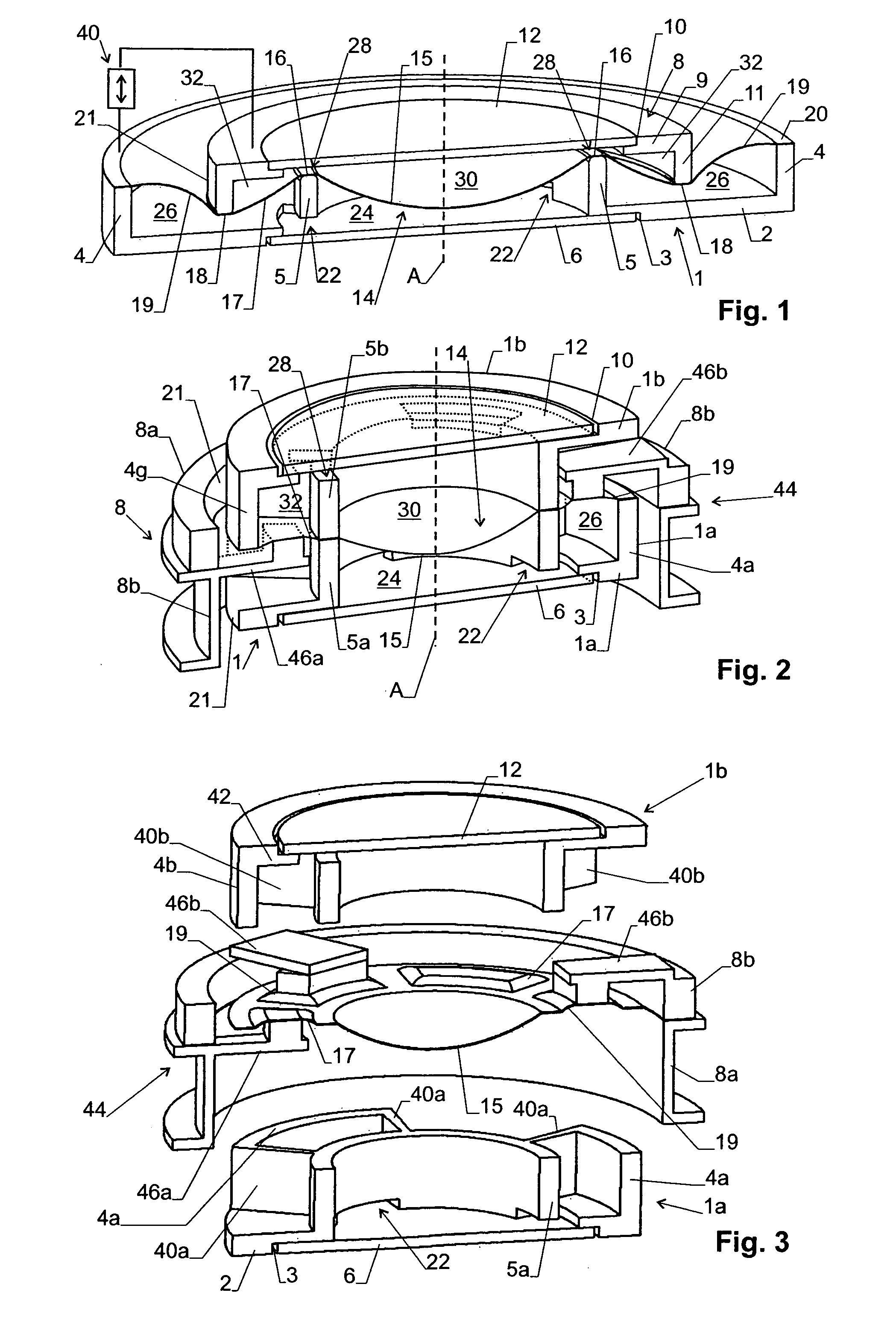
[0025]The embodiment of a variable focus lens of FIG. 1 is of substantially rotational-symmetric design in respect to an optical axis A. It comprises a housing 1 having a radially extending bottom section 2 with a first circular opening 3, a cylindrical, axially extending outer wall 4 and a cylindrical, axially extending inner wall or holder 5. A transparent first window 6 is held in housing 1 and closes first circular opening 3.

[0026]The lens further comprises an actuator 8 having a radially extending top section 9 with a second circular opening 10 and a cylindrical, axially extending outer wall 11. A transparent second window 12 is held in actuator 8 and closes second circular opening 10. The transparent second window 12 and the top section 9 can also be made out of one material and be one single component.

[0027]A flexible, elastic foil 14 extends between housing 1 and actuator 8 and forms a plurality of membranes. These membranes include:[0028]A primary membrane 15 suspended in h...

second embodiment

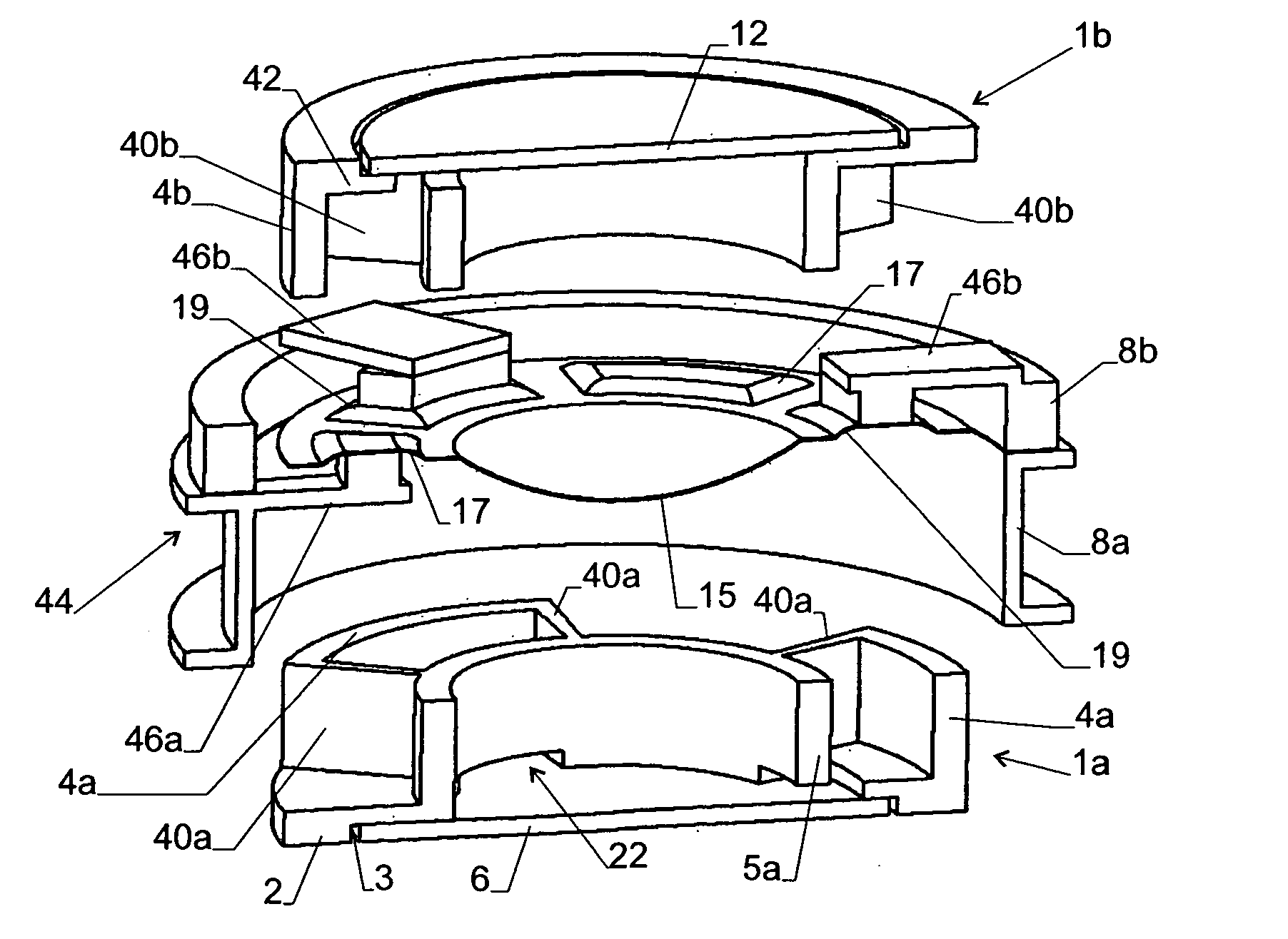
[0055]A second embodiment is shown in FIGS. 2 and 3. In the following, only the differences with respect to the first embodiment are described.

[0056]In the first embodiment the first and second auxiliary membranes 19, 17 are not arranged in an annular layout with one membrane at a larger distance from axis A than the other. Rather, as shown in FIGS. 2 and 3, the first and second auxiliary membranes 19, 17 are arranged on a common annular region in alternating fashion when viewed in azimuthal direction. They are meeting at radial wall sections 40a, 40b of housing 1.

[0057]As can be seen, housing 1 has two-part form, with a first, bottom section 1a and a second, top section 1b rigidly connected to each other, with the foil forming the membranes arranged between them. Both sections 1a, 1b together form holder 5 by means of inner wall sections 5a, 5b. The radial sections 40a, 40b are extending radially away from inner wall sections 5a, 5b, respectively.

[0058]Each pair of two wall section...


PUM

PropertyMeasurementUnit
sizeaaaaaaaaaa
sizeaaaaaaaaaa
sizeaaaaaaaaaa

Abstract

A variable focus lens has a housing (1) and an actuator (8) which are mutually displaceable along an optical axis (A) of the lens. A primary membrane (15) is arranged between a first chamber (24, 26) and a second chamber (30, 32), with the first and second chambers being filled with liquids of similar density but different indices of refraction. First and second auxiliary membranes (19, 17) are provided for volume compensation. The first auxiliary membrane (19) forms a wall section of the first chamber (24, 26), and the second auxiliary membrane (17) forms a wall section of the second chamber (30, 32), at least one or both of the auxiliary membranes facing environmental air at its outer side.

Description

TECHNICAL FIELD[0001]The invention relates to a variable focus lens having a first and a second chamber filled with liquids having different indices of refraction. The two chambers are separated by a primary membrane. The lens comprises a housing and an actuator. An axial movement of the actuator with respect to the housing causes the primary membrane to be deformed.[0002]The invention also relates to a method for manufacturing such a lens.BACKGROUND ART[0003]A lens of this type is shown in WO 2008 / 020356. The lens has two hermetically sealed chambers filled with different liquids of differing refractive indices but with similar density. The chambers are separated by a deformable membrane. An advantage of this design lies in the reduction of membrane deformations caused by gravity. However, the design described in WO 2008 / 020356 requires an indirect force transmission through a magnetic field to the membrane because the actuator is not readily accessible. In addition, manufacturing ...

Claims


Application Information

Patent Timeline
Patent Type & Authority Applications(United States)
IPC IPC(8): G02B3/14B29D11/00
CPCG02B3/14B29D11/00403G02B26/004G02B26/02
Inventor KERN, THOMAS
Owner OPTOTUNE AG
Features
  • Generate Ideas
  • Intellectual Property
  • Life Sciences
  • Materials
  • Tech Scout
  • Unparalleled Data Quality
  • Higher Quality Content
  • 60% Fewer Hallucinations
Learn More