
Wireless control apparatus, wireless terminal apparatus, wireless communication system, control program of wireless control apparatus and wireless terminal apparatus and integrated circuit

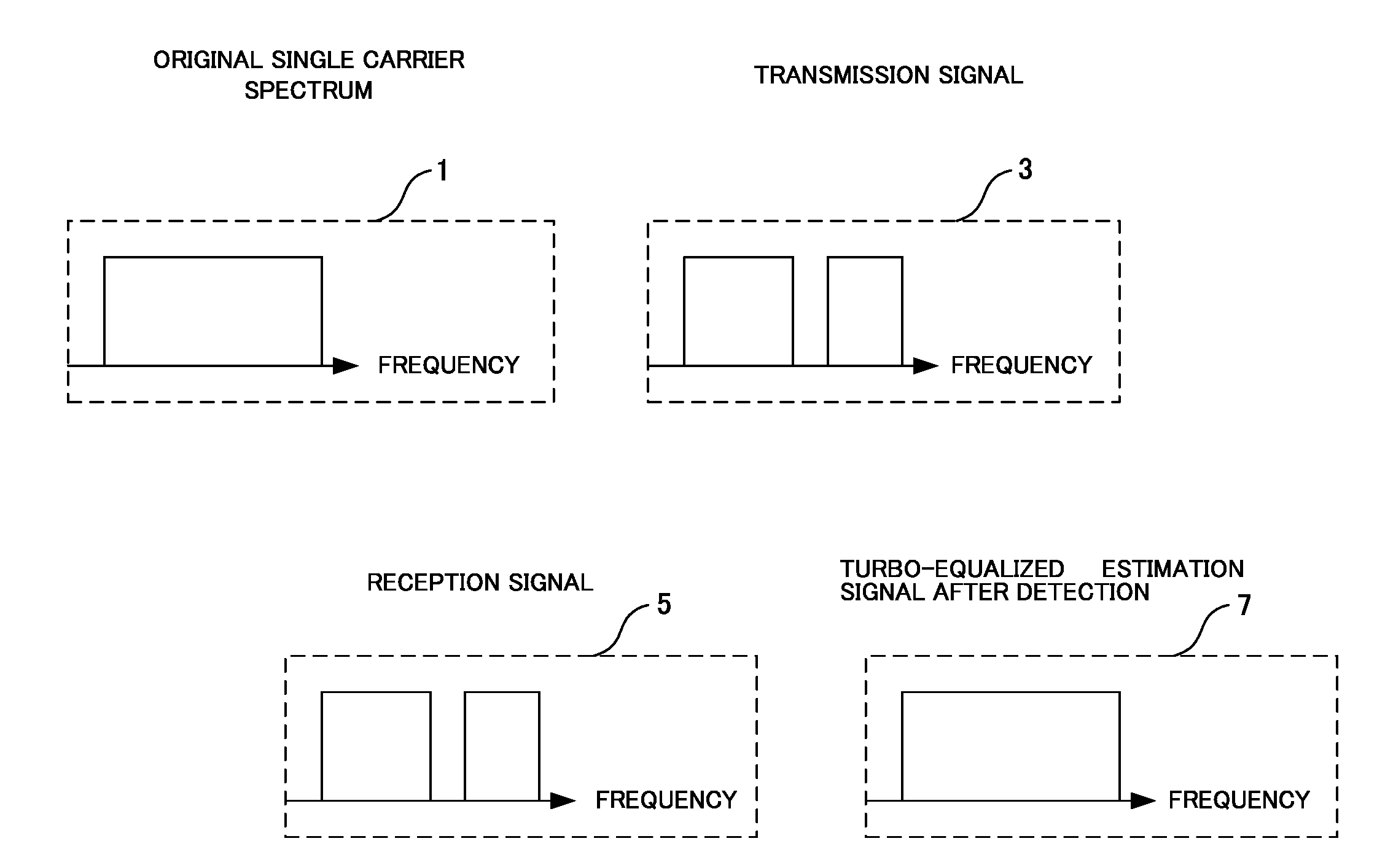
a control apparatus and terminal technology, applied in the field of spectrum efficiency improvement, can solve problems such as inability to improve spectrum efficiency, and achieve the effect of improving spectrum efficiency of the base station apparatus

Inactive Publication Date: 2013-10-10
SHARP KK
View PDF4 Cites 9 Cited by
  • Summary
  • Abstract
  • Description
  • Claims
  • Application Information

AI Technical Summary

Benefits of technology

The present invention is a wireless control system that improves spectrum efficiency in mobile stations that use multiple antennas. The system uses clipping to shape the transmission signal from the mobile station, which results in more efficient use of the available spectrum. This technology can be applied to improve the performance of base station equipment and mobile devices alike.

Problems solved by technology

However, a method of applying clipping to a multi-antenna technology (MIMO (Multiple-Input Multiple-Output) technology or the like) incorporating a plurality of transmission / reception antennas is not disclosed.
Hence, when the multi-antenna is used, it is impossible to improve spectrum efficiency by performing spectrum shaping including clipping on a transmission signal from a mobile station apparatus.

Method used


Image

  • Wireless control apparatus, wireless terminal apparatus, wireless communication system, control program of wireless control apparatus and wireless terminal apparatus and integrated circuit
  • Wireless control apparatus, wireless terminal apparatus, wireless communication system, control program of wireless control apparatus and wireless terminal apparatus and integrated circuit
  • Wireless control apparatus, wireless terminal apparatus, wireless communication system, control program of wireless control apparatus and wireless terminal apparatus and integrated circuit

Examples


first embodiment

2×1 Transmit Diversity

[0055]In the present embodiment, a method of determining, in common, a frequency to be clipped for each transmission antenna used for transmission will be described.

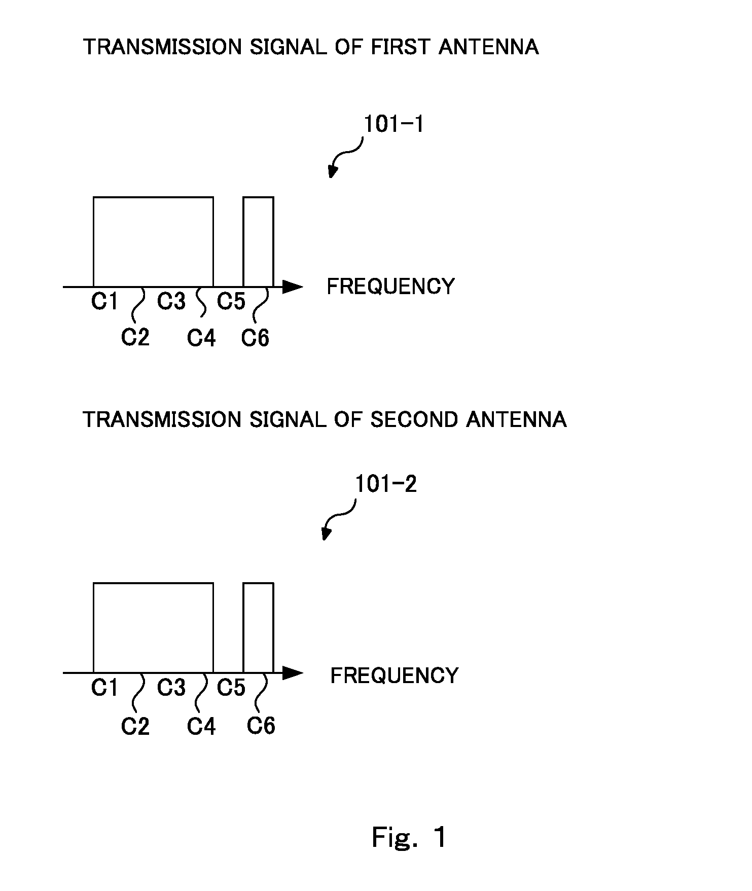
[0056]FIG. 1 is a diagram showing the concept of a case where a multi-antenna technology is applied to a spectrum clipping technology in the first embodiment of the present invention. In FIG. 1, it is assumed that discrete frequencies (subcarriers) allocated to a mobile station apparatus are present at 6 points, and that they are C1, C2, C3, C4, C5 and C6 in ascending order of frequency. The mobile station apparatus transmits a transmission signal 101-1 in a frequency domain from a first transmission antenna and a transmission signal 101-2 in a frequency domain from a second transmission antenna. Here, as shown in the drawing, each transmission antenna is assumed to perform the same clipping. Here, the spectrum having the signals allocated is C1, C2, C3, C4 and C6, and C5 is clipped. The signal arra...

second embodiment

In a Case where Precoding is Performed

[0068]In the present embodiment, a case where beam forming called precoding is applied will be described.

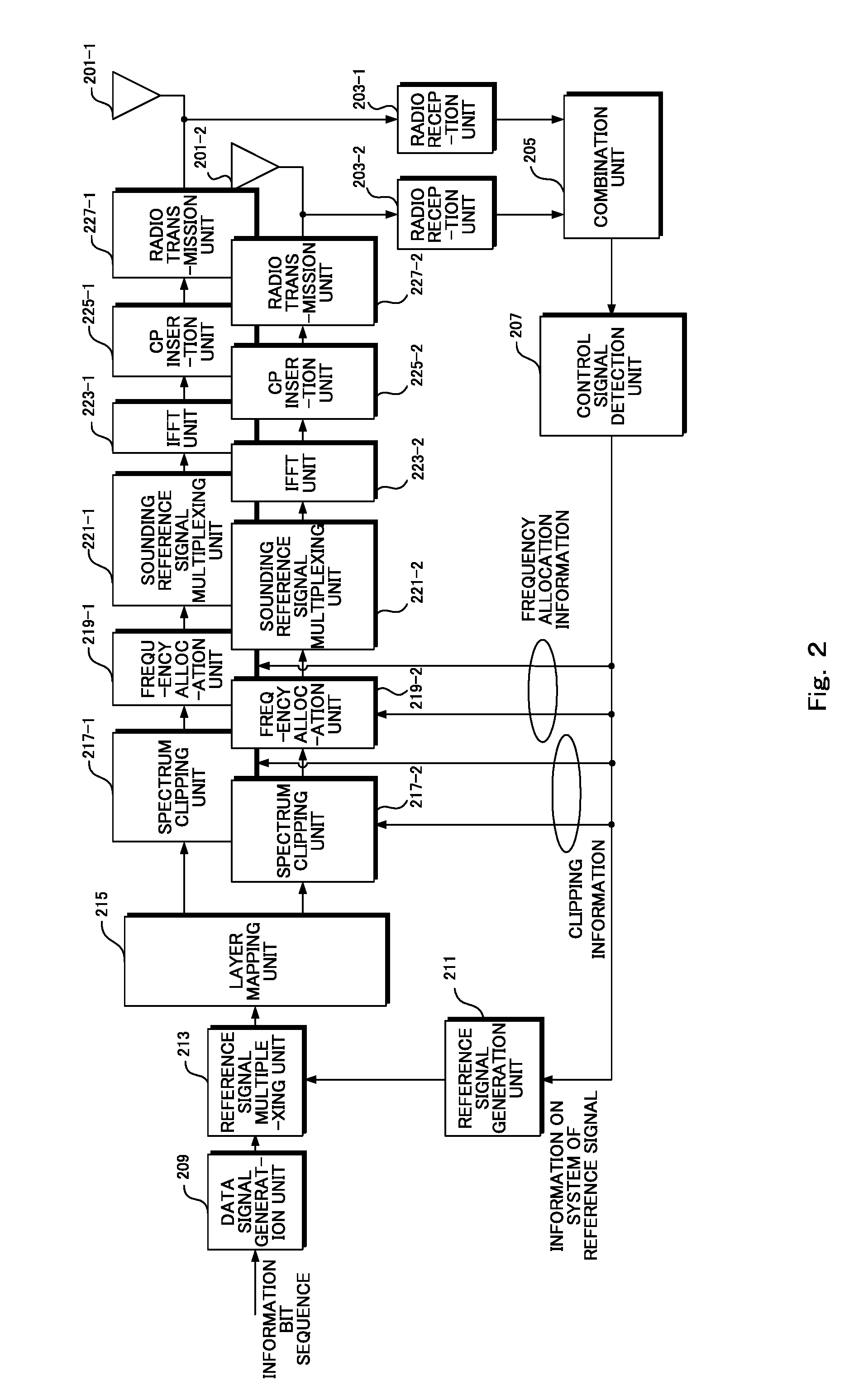
[0069]FIG. 5 is a block diagram showing an example of a mobile station apparatus according to the second embodiment of the present invention. As compared with FIG. 2, the layer mapping unit 215 is changed to a precoding unit 501. In the precoding unit 501, a previously defined precoding matrix is multiplied.

[0070]FIG. 6 is a table showing the precoding matrix in LTE-A. Here, a case where the number of transmission antennas is 2 is shown as an example. “Number of layers u” is a layer number, and, when the layer number is 1, two antennas 201 are used to transmit signals of one stream whereas when the layer number is 2, signals of two streams are transmitted. “Codebook index” is an index when which matrix is used for the mobile station apparatus is notified. Here, since rank 2 is described in an embodiment, which will be described later, a descr...

third embodiment

In the Case of MIMO

[0075]In the present embodiment, a case of MIMO will be described. Here, a case where two antennas 201 are used to perform transmission in rank 2 will be described.

[0076]FIG. 8 is a diagram showing an example of the concept of a frequency signal of each antenna in MIMO in a third embodiment of the present invention. FIG. 8 differs from FIG. 1 in that a transmission signal 701-1 and a transmission signal 701-2 are different signals.

[0077]FIG. 9 is a block diagram showing an example of a mobile station apparatus according to the third embodiment of the present invention. Here, a case where the number of information bit sequences called a code word is 1 will be described. In this case, in order to transmit two streams, an S / P (Serial to Parallel) unit 801 performs serial-to-parallel conversion. Then, in reference signal multiplexing units 803-1 and 803-2, reference signals for demodulation of each stream are multiplexed. Since the reference signals need to be separat...


PUM


Abstract

When a mobile station apparatus uses a multi-antenna, spectrum efficiency is improved with clipping performed on a transmission signal from the mobile station apparatus. There is provided a wireless control apparatus applied to a wireless communication system that performs clipping processing not to transmit a spectrum of part of a frequency domain so as to transmit and receive data, the wireless control apparatus, based on channel state information with a wireless terminal apparatus which is a destination, generates clipping information indicating a frequency domain where the clipping processing is performed and determines frequency allocation for the wireless terminal apparatus to generate frequency allocation information, and notifies the wireless terminal apparatus of the clipping information and the frequency allocation information.

Description

TECHNICAL FIELD[0001]The present invention relates to a spectrum clipping method when a multi-antenna is used.BACKGROUND ART[0002]The standardization of a LTE (Long Term Evolution) system that is the wireless communication system of the 3.9th generation mobile telephones has been almost completed, and LTE-A (LTE-Advanced) that is developed more than the LTE system has recently been standardized as one candidate of the fourth generation wireless communication system (referred also to as IMT-A). In general, since in the uplink (communication from a mobile station to a base station) of a mobile communication system, the mobile station functions as a transmission station, a single carrier scheme (in the LTE, a SC-FDMA (Single Carrier Frequency Division Multiple Access) scheme is adopted) is regarded to be effective, which can maintain the high power efficiency of an amplifier with a limited amount of transmit power and in which a peak power is low. The SC-FDMA is also referred to as a D...

Claims


Application Information

Patent Timeline
Patent Type & Authority Applications(United States)
IPC IPC(8): H04W72/04
CPCH04B7/06H04W72/0406H04W72/0453H04W72/042H04L1/0045H04W72/23H04W72/20
Inventor YOKOMAKURA, KAZUNARIHAMAGUCHI, YASUHIRONAKAMURA, OSAMUGOTO, JUNGOTAKAHASHI, HIROKI
Owner SHARP KK
Learn More