Thermal laser scribe cutting for electrochromic device production

Active Publication Date: 2013-10-10
SAGE ELECTROCHROMICS
View PDF9 Cites 66 Cited by
  • Summary
  • Abstract
  • Description
  • Claims
  • Application Information

AI Technical Summary

Benefits of technology

[0007]The disclosure provides for a method of laser scribing electrochromic panels such that reduces the amount o

Problems solved by technology

This would result in both a loss of useable area on the master panel as well as limit

Method used


Image

  • Thermal laser scribe cutting for electrochromic device production
  • Thermal laser scribe cutting for electrochromic device production
  • Thermal laser scribe cutting for electrochromic device production

Examples


Embodiment Construction

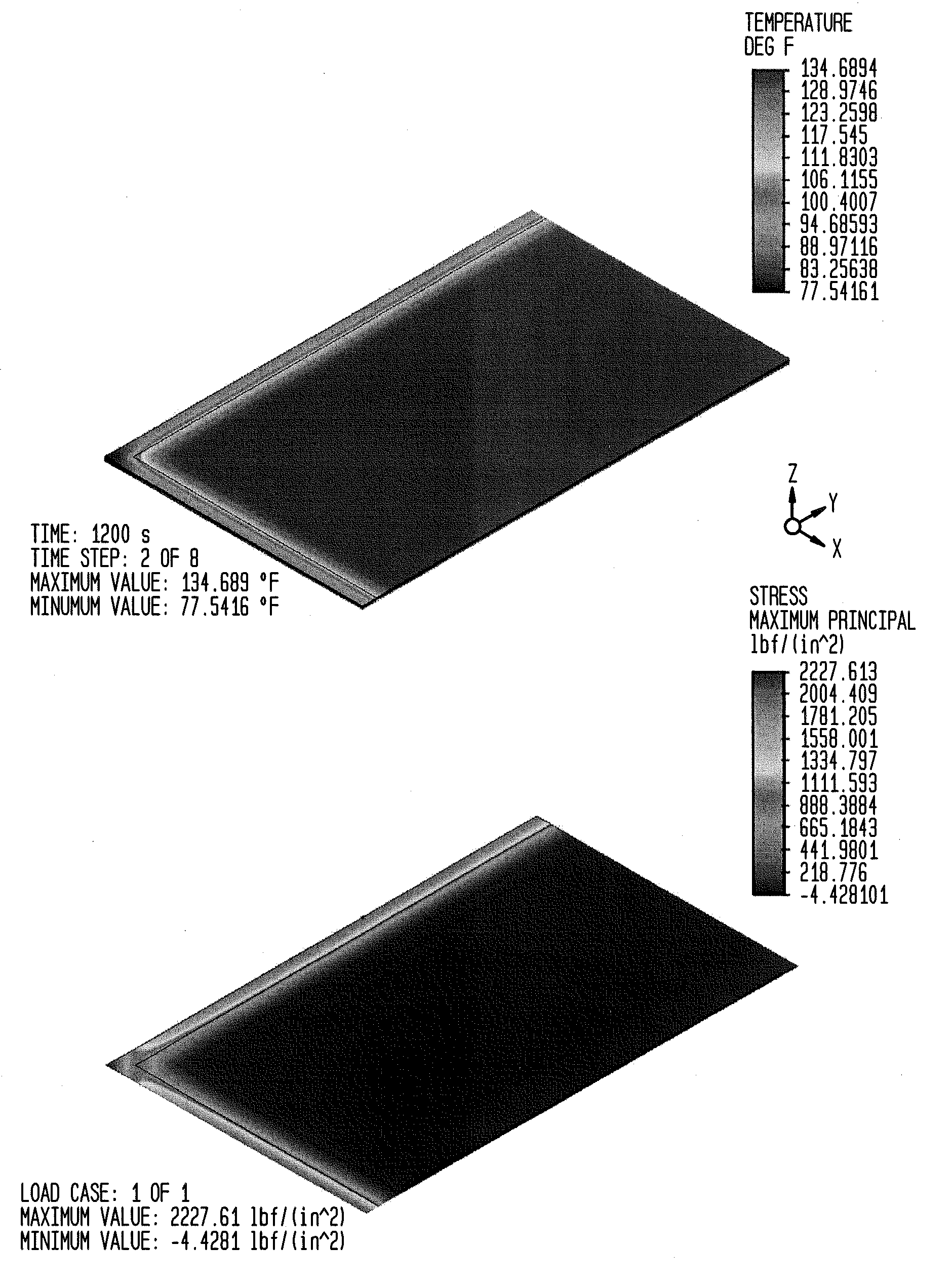
[0015]The cutting process of the present disclosure includes: (a) creating a starter crack using a scribe wheel, (b) application of laser heating, and (c) subsequent cooling from a gas or an aerosol jet, as the laser beam and cooling jet move along the desired cutting line. This process may be applied to a pane of glass, a laminate, or other substrate.

[0016]In some examples, the cutting process may involve electrothermal cutting in place of laser heating / scribing. Similarly, although the description presented herein describes an example cutting process involving a laser beam performing laser cutting, the laser beam may be replaced in those examples with an electrothermal cutting implement that focuses heat on a select portion of the substrate (i.e., in order to cut the substrate). The electrothermal cutting may then be followed with cooling from a gas or aerosol jet, as done in laser cutting methods, in the same manner as described below.

[0017]The cutting process begins by creating ...


PUM

PropertyMeasurementUnit
Lengthaaaaaaaaaa
Lengthaaaaaaaaaa
Lengthaaaaaaaaaa

Abstract

The disclosure is directed to a cutting process involving: (a) creating a starter crack using a scribe wheel, (b) application of laser or electrothermal heating, and (c) subsequent cooling from a gas or an aerosol jet, as the laser beam and cooling jet move along the desired cutting line. The cutting process can be implemented for cutting a glass panel or other substrate into a plurality of smaller panels. The starter crack may be created on any of the smaller panels within about 10 mm to about 20 mm from the corner of the smaller panel.

Description

CROSS-REFERENCE TO RELATED APPLICATIONS[0001]The present application claims the benefit of the filing date of U.S. Provisional Patent Application No. 60 / 620,713 filed Apr. 5, 2012, the disclosure of which is hereby incorporated herein by reference.FIELD OF THE INVENTION[0002]This invention maximizes the use of a cutting process, such as a laser cutting process, to separate daughter panels on a large EC panel by allowing the cut daughter panel to include the region associated with a starter crack.BACKGROUND OF THE INVENTION[0003]Electrochromic devices prepared as laminates are known in the art. By way of example only, a laser cutting process may be used to prepare electrochromic (EC) panels on 2.2 mm annealed float glass from a large master panel that will be laminated onto a heat-strengthened or tempered outer lite. A process for manufacturing an electrochromic device laminate is described in PCT application PCT / US2011 / 027148, the disclosure of which is hereby incorporated by refere...

Claims


Application Information

Patent Timeline
IPC IPC(8): C03B33/02
CPCC03B33/0222B28D5/0011B23K26/4075Y10T428/24C03B33/105C03B33/027C03B33/091B23K26/40B23K2103/50B23K26/402
Inventor GIRON, JEAN-CHRISTOPHEKALWEIT, HARVEYMCCOY, MICHAEL A.YEH, LI-YADOUCHE, JEAN-PIERRE
Owner SAGE ELECTROCHROMICS
Why Eureka
Try Eureka