Ground terminal assembly structure

a technology of assembly structure and ground terminal, which is applied in the direction of coupling device connection, coupling protective earth/shielding arrangement, connection contact member material, etc., can solve the problems of extra length and space occupation, and achieve the effect of preventing drag turning, short time, and simple production

Inactive Publication Date: 2013-10-10
SUMITOMO WIRING SYST LTD
View PDF11 Cites 6 Cited by
  • Summary
  • Abstract
  • Description
  • Claims
  • Application Information

AI Technical Summary

Benefits of technology

[0011]The extending ends of the barrels of the respective ground terminals are arranged close to one another or converge when the respective ground terminals are placed properly on and connected to the corresponding superimposing portions of the fitting. As a result, the ground wires drawn out from the respective barrels are close to each other at a position immediately behind the barrels. Specifically, the respective ground terminals are assembled in a specified positional relationship via the connecting fitting and the ground wires drawn out from the respective ground terminals are brought close to each other immediately behind the barrels. Therefore, the ground wires can be bundled efficiently into a harness and taped, clamped or arranged in a corrugated or heat-shrinkable tube.
[0012]The ground wires drawn out from the barrels could not be brought close to each other immediately behind the barrels if the barrels were parallel when the ground terminals are assembled to the fitting. Rather, the ground wires could be brought close to each other only after extending a certain distance straight. Thus, an extra length would be necessary and this extra length takes up space. However, the ground wires drawn out from the barrels of the ground terminal assembly structure of the invention come close to each other or converge at a position immediately behind the wire barrels. Thus, the ground wires need not have an extra length and space saving is realized.
[0013]The ground terminals are bolted at plural positions. However, the ground terminals are assembled via the fitting. Thus, operations of aligning and positioning the bolt insertion holes of the ground terminals with respect to the mating member can be performed at once, and a grounding operation can be performed efficiently.
[0017]Alternatively, the ground terminals may be formed so that the wire connection portions extend obliquely from the main portions to bring the extending ends close to each other and the fitting may be formed so that the superimposing portions are arranged laterally on a straight line. Thus, the linear fitting of this embodiment is simple to produce.
[0018]The assembled ground terminals and connecting fitting are fixed to the mating member by inserting bolts through the bolt insertion holes and screwing the bolts into nuts provided on the mating member or inserting stud bolts standing on the mating member through the bolt insertion holes and tightening nuts threadably engaged with the stud bolts. The assembly may be dragged to turn due to frictional engagement between the bolts or the nuts to be tightened and a fastening surface of the assembly. However, the fitting may have a drag turning preventing piece that is engageable with a mating member to which the fitting is to be bolted for preventing drag turning during bolting. Therefore, the bolts or the nuts can be tightened efficiently, and an operation of fixing the assembly to the mating member can be performed in a short time.

Problems solved by technology

Thus, an extra length would be necessary and this extra length takes up space.

Method used


Image

  • Ground terminal assembly structure
  • Ground terminal assembly structure
  • Ground terminal assembly structure

Examples


first embodiment

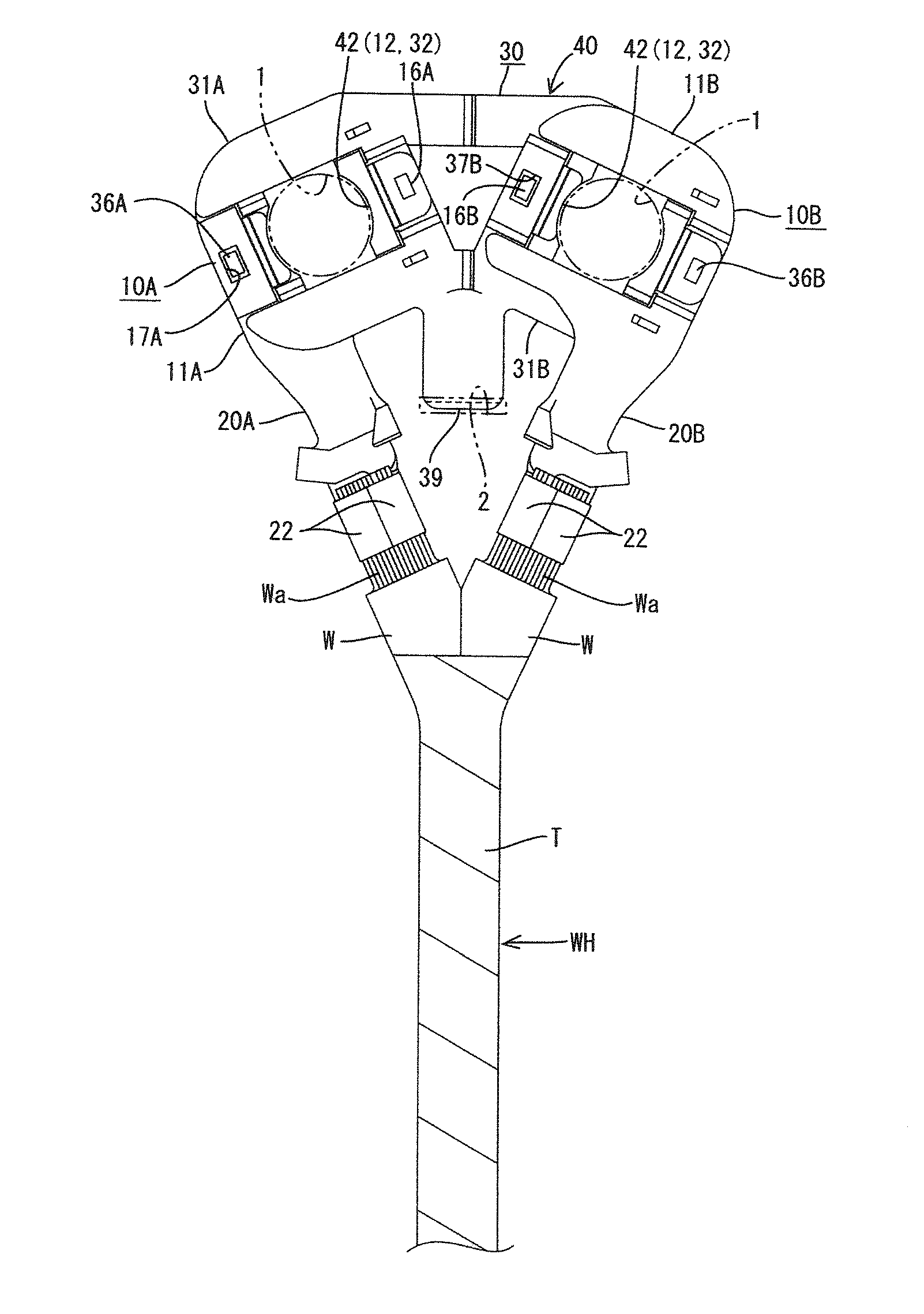
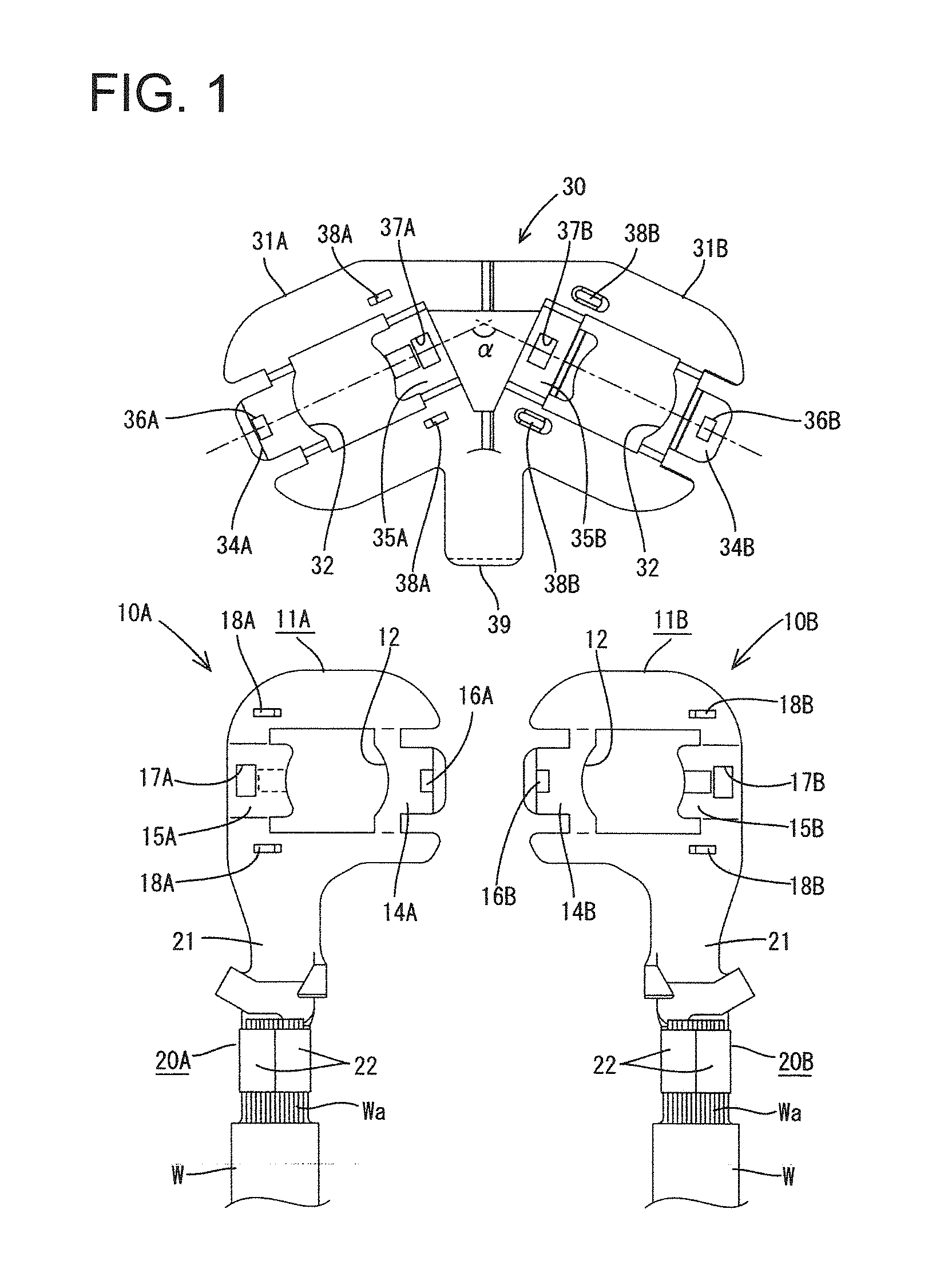
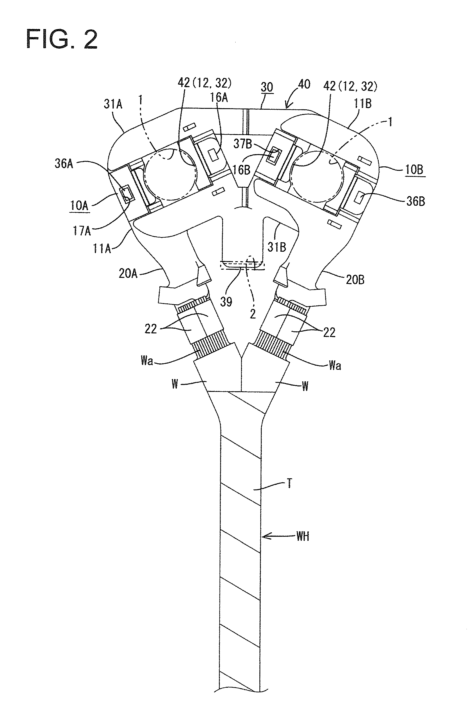
[0026]the invention is described with reference to FIGS. 1 to 3. As shown in FIG. 1, this first embodiment includes a first ground terminal 10A and a second ground terminal 10B, which are laterally paired, and a fitting 30 with which the ground terminals 10A, 10B are to be assembled. The both ground terminals 10A, 10B particularly substantially have the same shapes as existing ones which are placed one on the other and grounded to a body of an automotive vehicle by bolting.

[0027]The ground terminals 10A, 10B particularly are formed to have substantially bilaterally symmetrical outer shapes e.g. by particularly press-working a conductive metal plate with excellent electrical conductivity and / or include a substantially rectangular main portion 11A, 11B formed with a bolt insertion hole 12 substantially in the center and a wire connection portion comprising at least one wire barrel 20A, 20B substantially extending back (down in FIG. 1) from the base end edge of the main portion 11A, 11...

second embodiment

[0053]the invention is described with reference to FIGS. 4 to 6. In this second embodiment, the shape of a connecting fitting 55 and the postures of wire barrels 52A, 52B provided on ground terminals 50A, 50B are changed as compared with the first embodiment.

[0054]Points of difference from the first embodiment are mainly described below and parts and the like having the same or similar configuration and / or the similar or same functions as in the first embodiment are denoted by the same reference signs and not described or only briefly described.

[0055]The wire barrels 52A, 52B provided on the (left and right) ground terminals 50A, 50B substantially extend backward from positions at sides distant from the mating ground terminals on the base end edges of main portions 11A, 11B near end parts as in the above first embodiment. However, the wire barrels 52A, 52B are in a posture inclined inwardly by an angle of between about 15° to about 35° (e.g. of about 25°) so that parts of the barrel...


PUM


Abstract

A ground terminal assembly includes ground terminals (10A, 10B) and a connecting fitting (30). Each ground terminal (10A, 10B) has a main portion (11A, 11B) with a bolt insertion hole (12). A barrel (20A, 20B) extends from the main portion (11A, 11B) and can be crimped to a ground wire W. The connecting fitting (30) has superimposing portions (31A, 31B) formed with bolt insertion holes (32) and on which the main portions (11A, 11B) of the ground terminals (10A, 10B) are placed. The barrels (20A, 20B) of the ground terminals (10A, 10B) are arranged so that their extending ends (22) come close to each other when the main portions (11A, 11B) of the ground terminals (10A, 10B) are placed on and connected to the corresponding superimposing portions (31A, 31B) of the connecting fitting (30) at positions where the bolt insertion holes (12, 32) align.

Description

BACKGROUND[0001]1. Field of the Invention[0002]The invention relates to a ground terminal assembly structure.[0003]2. Description of the Related Art[0004]A plurality of vehicle mounted devices conventionally are grounded by connecting ground terminals to ends of ground wires drawn out from the respective devices, placing the ground terminals one above another on a body or the like of an automotive vehicle and fixing the ground terminals to the body by a bolt.[0005]Ground terminals that are bolted at one position may not be grounded precisely if the bolt is loosened due to vibration or the like. Accordingly, Japanese Unexamined Patent Publication No. 2004-253167 discloses bolting ground terminals at two positions. More particularly, left and right ground terminals are proposed in this literature. Each ground terminal has a main portion in the form of a wide plate. Two bolt insertion holes are formed at a predetermined distance from each other in the main portion, and barrels to be cr...

Claims


Application Information

Patent Timeline
Patent Type & Authority Applications(United States)
IPC IPC(8): H01R13/652
CPCH01R4/34H01R11/12H01R2201/26H01R4/64H01R13/652H01R11/09
Inventor HORIUCHI, HIDEFUMI
Owner SUMITOMO WIRING SYST LTD
Why Eureka
Try Eureka