Phototherapy apparatus

a technology of phototherapy and apparatus, which is applied in the field of phototherapy apparatus, can solve the problems of unsatisfactory direct entry of intense light into the eye of a patient, and achieve the effects of improving the energy efficiency of the phototherapy apparatus, suitable therapeutic treatment, and intensive supply to the treatment par

Inactive Publication Date: 2013-10-10
PANASONIC HEALTHCARE HLDG CO LTD
View PDF0 Cites 0 Cited by
  • Summary
  • Abstract
  • Description
  • Claims
  • Application Information

AI Technical Summary

Benefits of technology

[0013]In the phototherapy apparatus according to the present invention, the light guide member has softness, and hence is deformed according to the shape of a treatment part when the treatment part is merely disposed so as to be brought into contact with the light guide member disposed on the surface of the light guide body. Thereby, a bent part, such as a finger joint, can be brought into contact with the light guide member without requiring a patient to perform an unnatural action. Further, light having entered the inside of the light guide body can be supplied to the treatment part via the light guide member. As a result, sufficient therapeutic light can be supplied to a bent part, such as a finger joint, and thereby suitable therapeutic treatment can be performed.
[0014]Further, in a conventional phototherapy apparatus, when a hand is placed on a light guide body to supply light to a finger joint as a treatment part of therapeutic treatment of rheumatism, parts of the hand other than the finger joint are in contact with the light guide body, and hence are also supplied with light. On the other hand, in the phototherapy apparatus according to the present invention, the light guide member is disposed on the surface of the light guide body, and hence light can be intensively supplied to the treatment part. As a result, the energy efficiency of the phototherapy apparatus can also be improved. Further, even when therapeutic treatment needs to be intensively applied to the finger joint portion, therapeutic light can be highly efficiently supplied to the finger joint portion, and hence an improvement in therapeutic efficacy can also be expected.
[0015]Further, in the phototherapy apparatus according to the present invention, when an inexpensive and general-purpose material, such as silicone, resin, is used as the material of the light guide member, the light guide member can be used as a disposable member, and hence therapeutic treatment in consideration of sanitation can be performed.

Problems solved by technology

However, the intensity of the light used for such therapy is strong, and hence the direct entry of intense light to the eye of a patient is not desirable.

Method used


Image

  • Phototherapy apparatus
  • Phototherapy apparatus
  • Phototherapy apparatus

Examples


embodiment 1

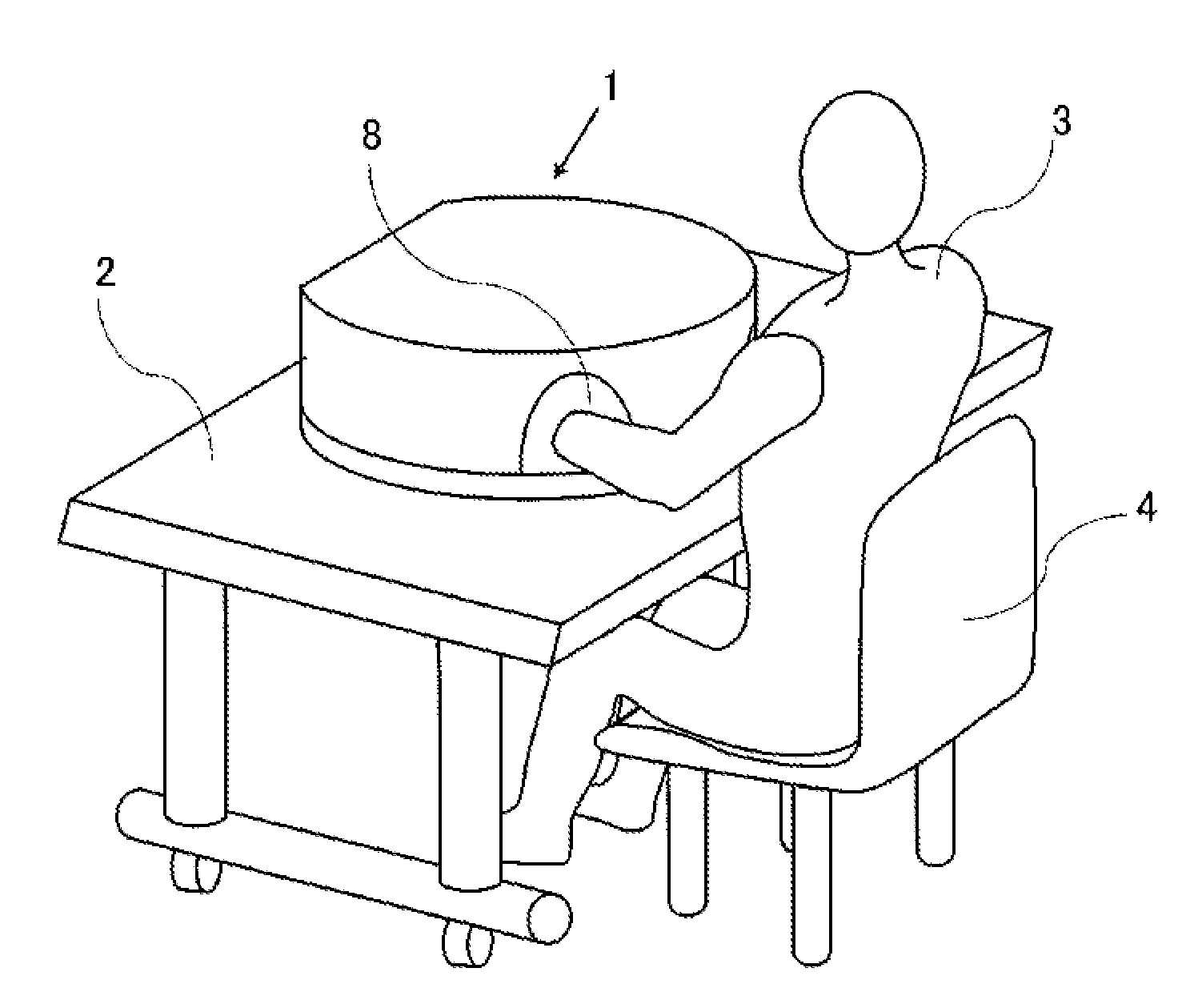
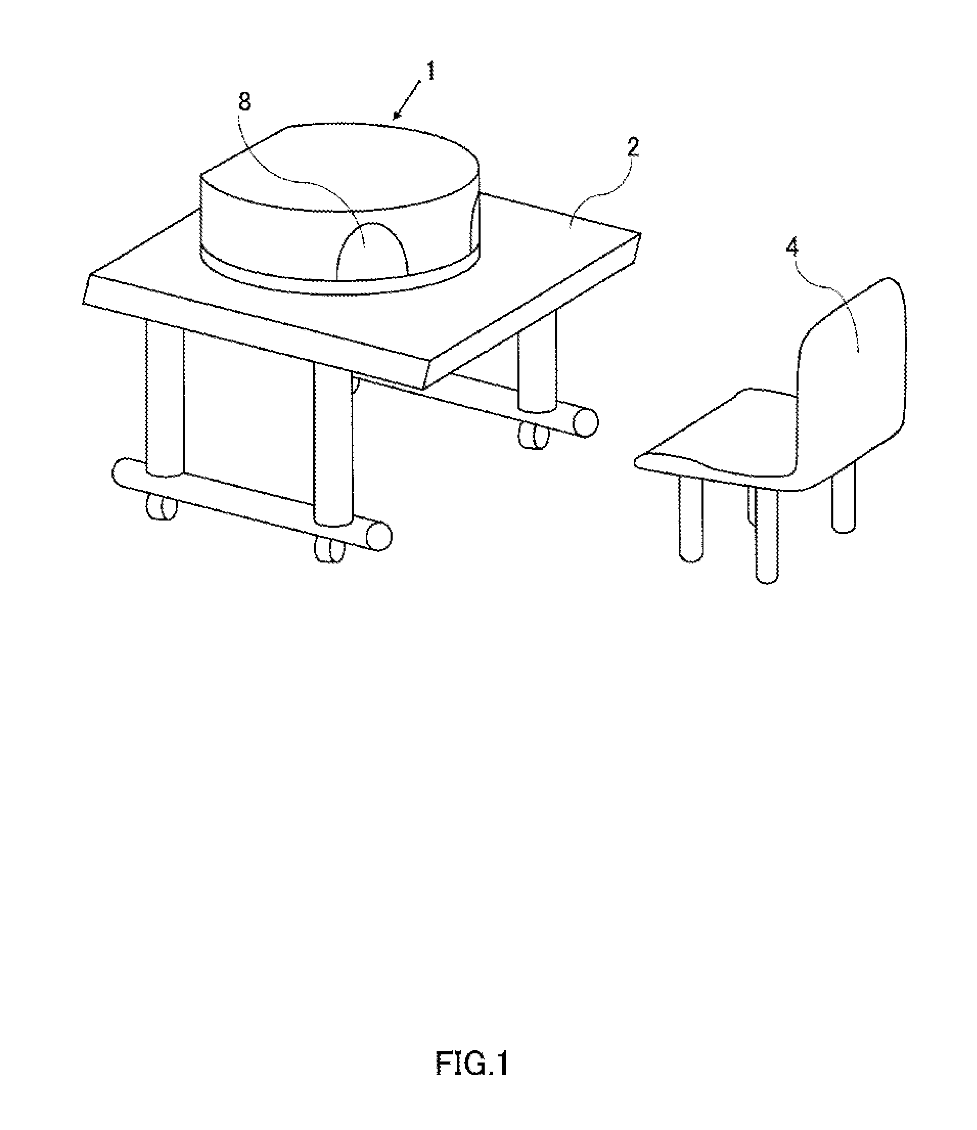
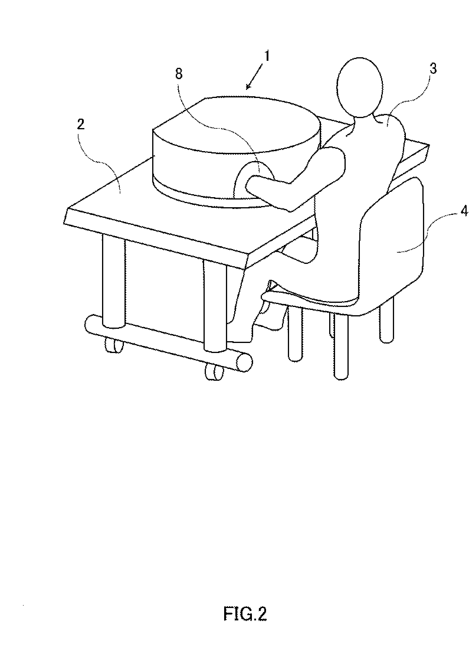
[0043]FIG. 1 is a perspective view illustrating a phototherapy apparatus according to Embodiment 1 of the present invention. Phototherapy apparatus 1 is mounted on desk 2. As shown in FIG. 2, patient 3 can sit on chair 4 and receive phototherapy using phototherapy apparatus 1 in his / her house or in a hospital.

[0044]As shown in FIGS. 3 and 4, phototherapy apparatus 1 includes disc-like base 5 and lid 6. Lid 6 has a capped cylindrical shape whose lower surface is open. Lid 6 is connected to base 5 by hinge 7, and can cover the surface of base 5 in an openable and closable manner. When the surface of base 5 is covered by lid 6, intense light for use in phototherapeutic treatment can be prevented from directly entering the eye of the patient 3.

[0045]Left and right two affected part insertion ports 8 are provided on the front surface side of the outer peripheral surface of lid 6, that is, on the side opposite to hinge 7. Further, hook 10 is provided on the front side of the outer periphe...

embodiment 2

[0086]Embodiment 2 as a modification of Embodiment 1 describes a configuration in which the relationship in the refractive index between light guide body 12 and light guide member 18 of auxiliary light guide body 13 is set as expressed by Equation 2. The other parts of the configuration are the same as those in Embodiment 1, and hence explanation thereof is omitted.

[2]

Refractive index of air

[0087]The material of light guide body 12 is a material which is transparent to the light from light source 17, and which has a refractive index higher than the refractive index (1.0) of air and lower than the refractive index of the biological tissue. Examples of such material include perfluoro resin, silicone resin having a refractive index adjusted to 1.4 or less, FEP (tetrafluoroethylene-hexafluoropropylene copolymer) resin, polytetrafluoroethylene, and the like.

[008...

embodiment 3

[0096]As shown in FIGS. 14 and 15, Embodiment 3 is different in the configuration of auxiliary light guide body 13 from Embodiment 1 and Embodiment 2. The other parts of the configuration are the same as those in Embodiment 1 and Embodiment 2, and hence explanation thereof is omitted. Further, the materials of light guide body 12 and light guide member 18 are not particularly limited as long as the materials have light-guiding properties. However, in Embodiment 3, a case is described in which the refractive indexes of the materials have the same relationship (see Equation 2) as that in Embodiment 2.

[0097]Auxiliary light guide body 13 in Embodiment 3 is illustrated in FIGS. 16 and 17. FIG. 16 is a perspective view of auxiliary light guide body 13. FIG. 17 is a longitudinal cross-sectional view of auxiliary light guide body 13.

[0098]Auxiliary light guide body 13 is configured by light guide member 18 and reflection film 20. Light guide member 18 is substantially sheet-shaped. The surf...


PUM


Abstract

Provided is a phototherapy apparatus capable of applying appropriate treatment. Specifically, the purpose of the present invention is to provide a phototherapy apparatus capable of easily supplying adequate treatment light even when a region to be treated is a bent region like finger joints of a patient having severe rheumatoid arthritis, thus making it possible to apply appropriate treatment. This phototherapy apparatus is configured to include: a light guide including a first surface on which an affected part is placed and a second surface on a back surface side of the first surface; a light source that outputs therapeutic light to enter an inside of the light guide body; and a light guide member that has softness and surface tackiness and is disposed on a part of the first surface.

Description

TECHNICAL FIELD[0001]The present invention relates to a phototherapy apparatus.BACKGROUND ART[0002]Phototherapy apparatuses, using, for example, infrared light (about 700 to 2500 nm) as therapeutic light, are used to alleviate pain due to chronic non-infectious inflammation in muscles and joints or to treat rheumatoid arthritis. These conventional phototherapy apparatuses are so configured as to apply therapeutic light from a light source onto a part to be treated (treatment part) in a non-contact manner either directly or via a light guide path (see, e.g., PTL 1). However, the intensity of the light used for such therapy is strong, and hence the direct entry of intense light to the eye of a patient is not desirable.[0003]To cope with this problem, there has been proposed a configuration in which, in the state where therapeutic light from a light source is introduced into a light guide body, such as acrylic and glass, a treatment part is brought into contact with the surface of the ...

Claims


Application Information

Patent Timeline
Patent Type & Authority Applications(United States)
IPC IPC(8): A61N5/06
CPCA61N5/0613A61N2005/0643A61N2005/063
Inventor KAWASE, YUKIII, YOSHITERUOKAMURA, DAISUKE
Owner PANASONIC HEALTHCARE HLDG CO LTD
Why Eureka
Try Eureka