Composite prosthetic devices

a prosthetic device and composite technology, applied in the field of prosthetic devices, can solve the problems of difficult to cover the geometries of stents, mechanical properties, and difficulty in manipulating certain properties of conventional devices,

Inactive Publication Date: 2013-10-10
ZEUS INDUSTRIAL PRODUCTS INC
View PDF2 Cites 64 Cited by
  • Summary
  • Abstract
  • Description
  • Claims
  • Application Information

AI Technical Summary

Benefits of technology

[0020]The methods described herein can provide composite prosthetic devices with varying compositions and properties. In some embodiments, the second electrospun polymer comprises a solution-electrospun polymer. In some embodiments, the second electrospun polymer comprises unsintered poly(tetrafluoroethylene). Advantageously, where the composite device comprises unsintered poly(tetrafluoroethylene), the method further comprises sintering the composite prosthetic device following the applying step.

Problems solved by technology

However, it is difficult with conventional devices to manipulate certain properties such as mechanical properties, cellular proliferation, cellular permeability, fluid permeability, adhesion to a structural frame, and / or incorporation of one or more active therapeutic components.
Although coverings can sometimes be used to alter the properties of devices, stents generally have complex geometries that cannot be readily covered with covering materials such as ePTFE.

Method used


Image

  • Composite prosthetic devices
  • Composite prosthetic devices
  • Composite prosthetic devices

Examples


example 1

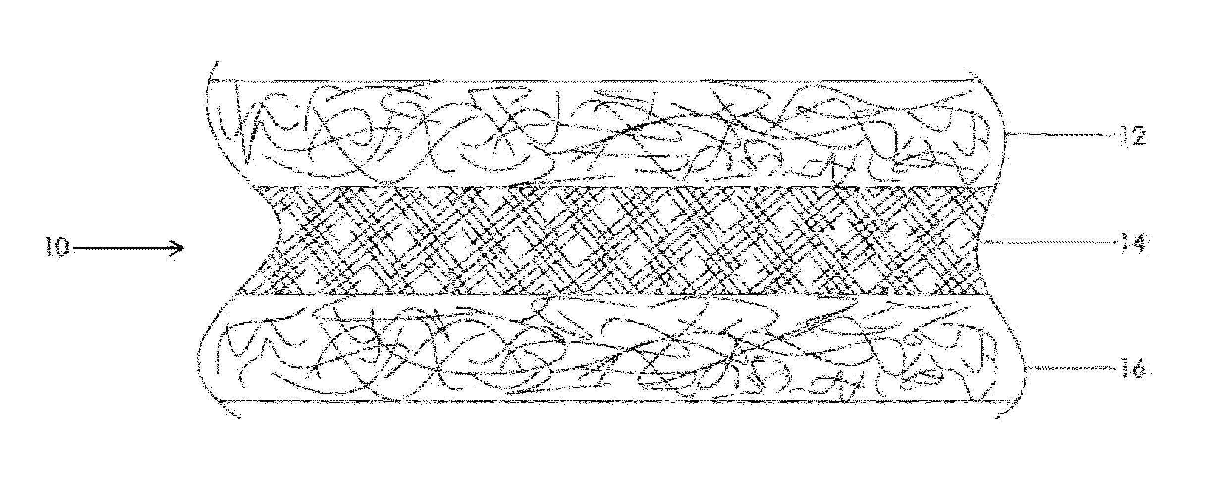
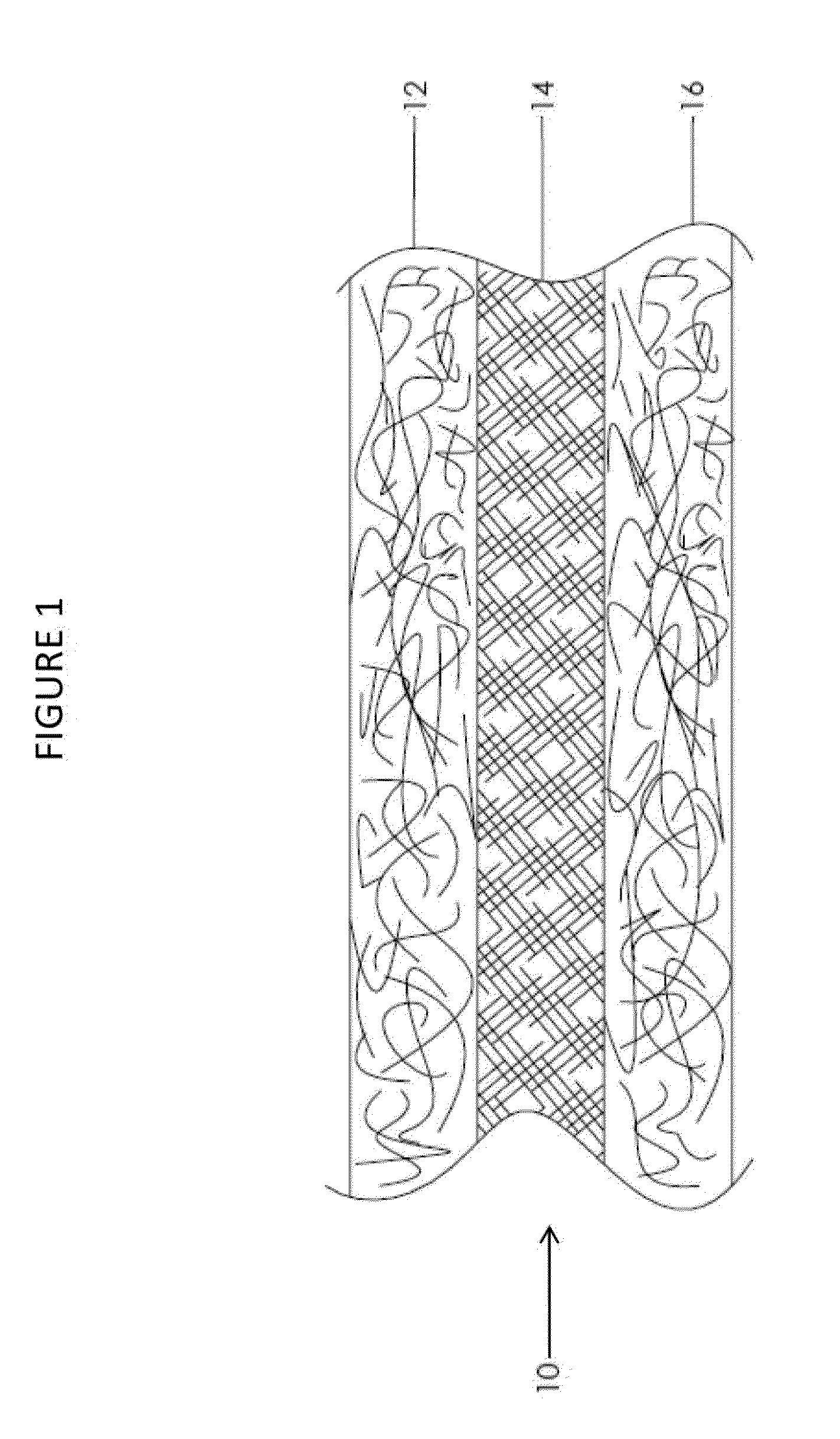
Espun PTFE / Espun PTFE / Espun PTFE

[0116]An espinning dispersion based on a mixture of 5.2% (PEO / PTFE) 300,000 amu polyethylene oxide and Daikin DX-9030, 60% PTFE dispersion in water is prepared, allowed to homogenize, and turned and filtered to achieve a smooth consistency. A 0.002″ thick stainless steel foil sheet (15.5″×17.5″) is mounted on a conductive fabric. The stainless foil is passed into the espinning chamber where PTFE fibers are to be deposited. The dispersion is espun using a total potential of 80 kV to facilitate formation of PTFE fibers, which collect in random formation on the stainless steel foil. The stainless steel foil containing the PTFE membrane is removed from the fabric and sintered at 385° C. until fully sintered (e.g., about 5 minutes).

[0117]The 0.0008″ sintered espun PTFE sheet, removed from the stainless foil, is wrapped twice around a 0.50″ exterior diameter (OD) stainless steel hypotube. The electrospinning process is repeated to give a second espun PTFE s...

example 2

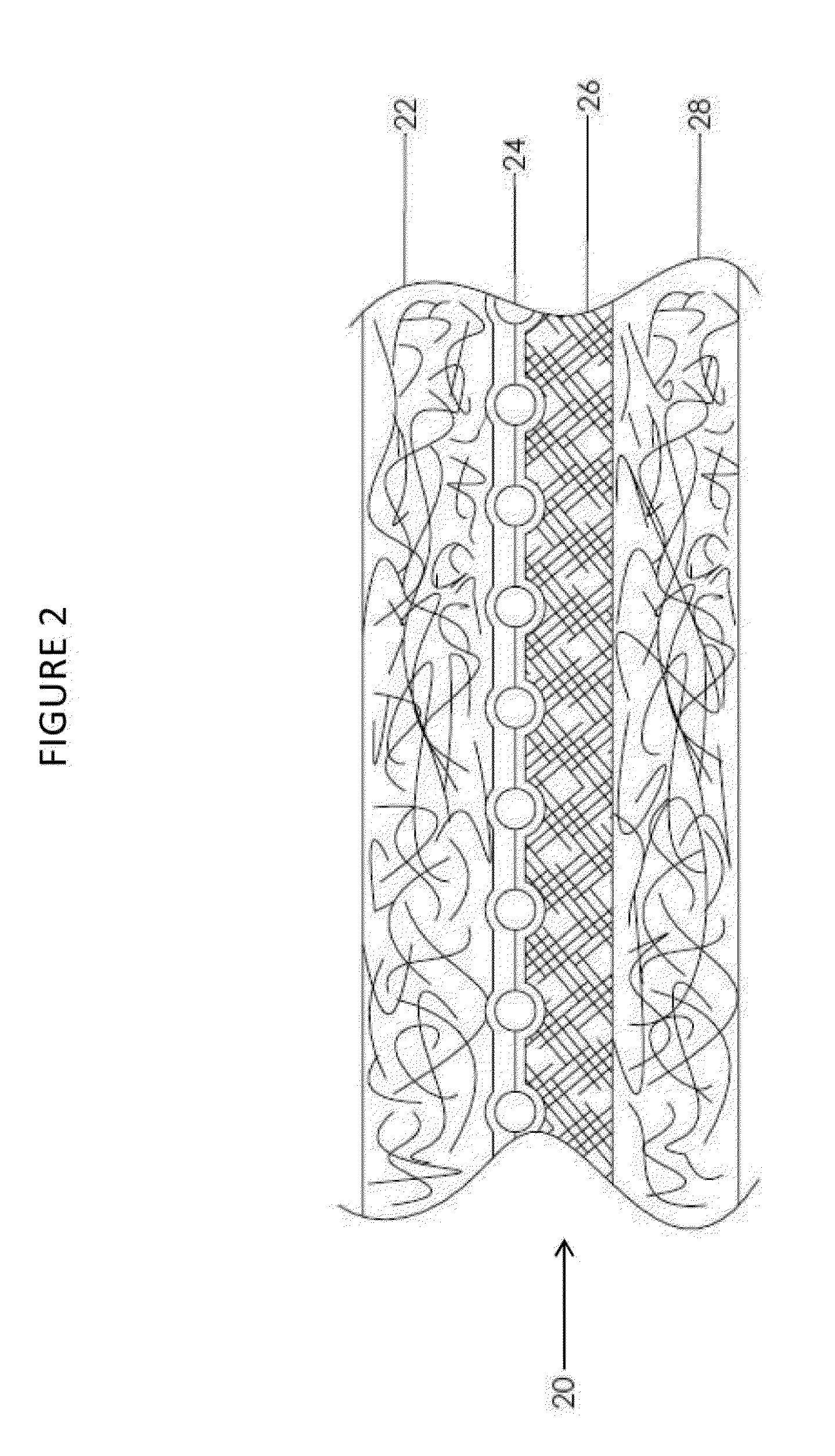
Espun PTFE / Stent / Espun PTFE / Espun PTFE

[0118]Example 2 is made similarly to Example 1 with the addition of a wire stent frame as an additional layer of the composite. An espinning dispersion based on a mixture of 5.2% (PEO / PTFE) 300,000 amu polyethylene oxide and Daikin DX-9030, 60% PTFE dispersion in water is prepared, allowed to homogenize, and turned and filtered to achieve a smooth consistency. A 0.002″ thick stainless steel foil sheet (15.5″×17.5″) is mounted on a conductive fabric. The stainless foil is passed into the espinning chamber where PTFE fibers are to be deposited. The dispersion is espun using a total potential of 80 kV to facilitate formation of PTFE fibers, which collect in random formation on the stainless steel foil. The stainless steel foil containing the PTFE membrane is removed from the fabric and sintered at 385° C. for 5 minutes.

[0119]The 0.0008″ sintered espun PTFE sheet, removed from the stainless foil, is wrapped twice around a 0.50″ exterior diameter (OD...

example 3

Espun PTFE / Espun PVDF / Espun PTFE

[0120]An espinning dispersion based on a mixture of 5.2% (PEO / PTFE) 300,000 amu polyethylene oxide and Daikin DX-9030, 60% PTFE dispersion in water is prepared, allowed to homogenize, and turned and filtered to achieve a smooth consistency. A 0.002″ thick stainless steel foil sheet (15.5″×17.5″) is mounted on a conductive fabric roll with a payoff and take-up mounted above a spinning electrode. A total potential of 80 kV is employed to facilitate formation of PTFE fibers, which collect in random formation on the stainless steel foil. The stainless steel foil containing the PTFE membrane is removed from the fabric and sintered (if desired) at 385° C. for 5 minutes.

[0121]A 0.0015″ thick stainless foil sheet 17″×18.5″ is wrapped around a rotating drum. The drum assembly is placed into a rotating chuck such that it is positioned to allow espinning along the entire length of the turning drum assembly. An espinning solution based on a mixture of 25% Atofina...


PUM

PropertyMeasurementUnit
temperatureaaaaaaaaaa
diametersaaaaaaaaaa

Abstract

The present disclosure provides composite prosthetic devices comprising two or more layers of electrospun polymers and methods of preparation thereof. In some embodiments, the two or more layers can be porous and in other embodiments, one or more components is nonporous. The composite prosthetic devices can comprise various materials and the properties of the prosthetic devices can be tailored for use in a range of different applications.

Description

CROSS-REFERENCE TO RELATED APPLICATIONS[0001]The present application claims priority to U.S. provisional patent application No. 61 / 620,633, filed Apr. 5, 2012 and U.S. provisional patent application No. 61 / 724,731, filed Nov. 9, 2012, which are both incorporated herein by reference in their entireties.FIELD OF THE INVENTION[0002]The invention is generally related to prosthetic devices and to methods of making and using such prosthetic devices.BACKGROUND[0003]The successful use of extruded tubes of expanded polytetrafluoroethylene (ePTFE) as synthetic implantable vascular prostheses or tubular grafts is well known and documented. ePTFE, which has been validated through numerous clinical studies, is particularly suited for this purpose as it exhibits superior bio-compatibility and can be mechanically manipulated to form a well-defined porous microstructure known to promote endothelialization. Further, ePTFE has been proven to exhibit a low thrombogenic response in vascular application...

Claims


Application Information

Patent Timeline
Patent Type & Authority Applications(United States)
IPC IPC(8): A61F2/06A61F2/86
CPCA61F2/06D04H1/728A61L31/10A61L31/146D01D5/003D01D10/02D01F6/12A61L2400/12A61L2420/08A61F2/86C08L27/18C08L75/04C08L83/04A61F2/0077A61F2/07A61F2002/0086A61F2002/072D10B2321/042D10B2509/06
Inventor PUCKETT, SABRINA D.MANASCO, JOSHUABALLARD, ROBERT L.ANNEAUX, BRUCE L.
Owner ZEUS INDUSTRIAL PRODUCTS INC
Why Eureka
Try Eureka