Continuous CFRP Decked Bulb T Beam Bridges For Accelerated Bridge Construction

a bridge and accelerated technology, applied in the field of bridges, can solve problems such as difficulties in transporting load members, limit the length and number of spans,

Active Publication Date: 2013-10-17
LAWRENCE TECHNOLOGICAL UNIV
View PDF7 Cites 21 Cited by
  • Summary
  • Abstract
  • Description
  • Claims
  • Application Information

AI Technical Summary

Problems solved by technology

If precast, the only limits to the length and number of spans may be the difficulties in transporting the load member to the bridge site.

Method used


Image

  • Continuous CFRP Decked Bulb T Beam Bridges For Accelerated Bridge Construction
  • Continuous CFRP Decked Bulb T Beam Bridges For Accelerated Bridge Construction
  • Continuous CFRP Decked Bulb T Beam Bridges For Accelerated Bridge Construction

Examples


Embodiment Construction

Proposed Solution

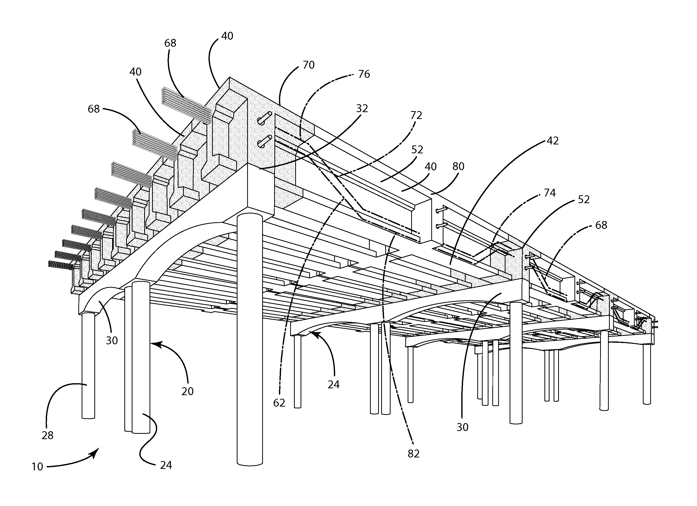
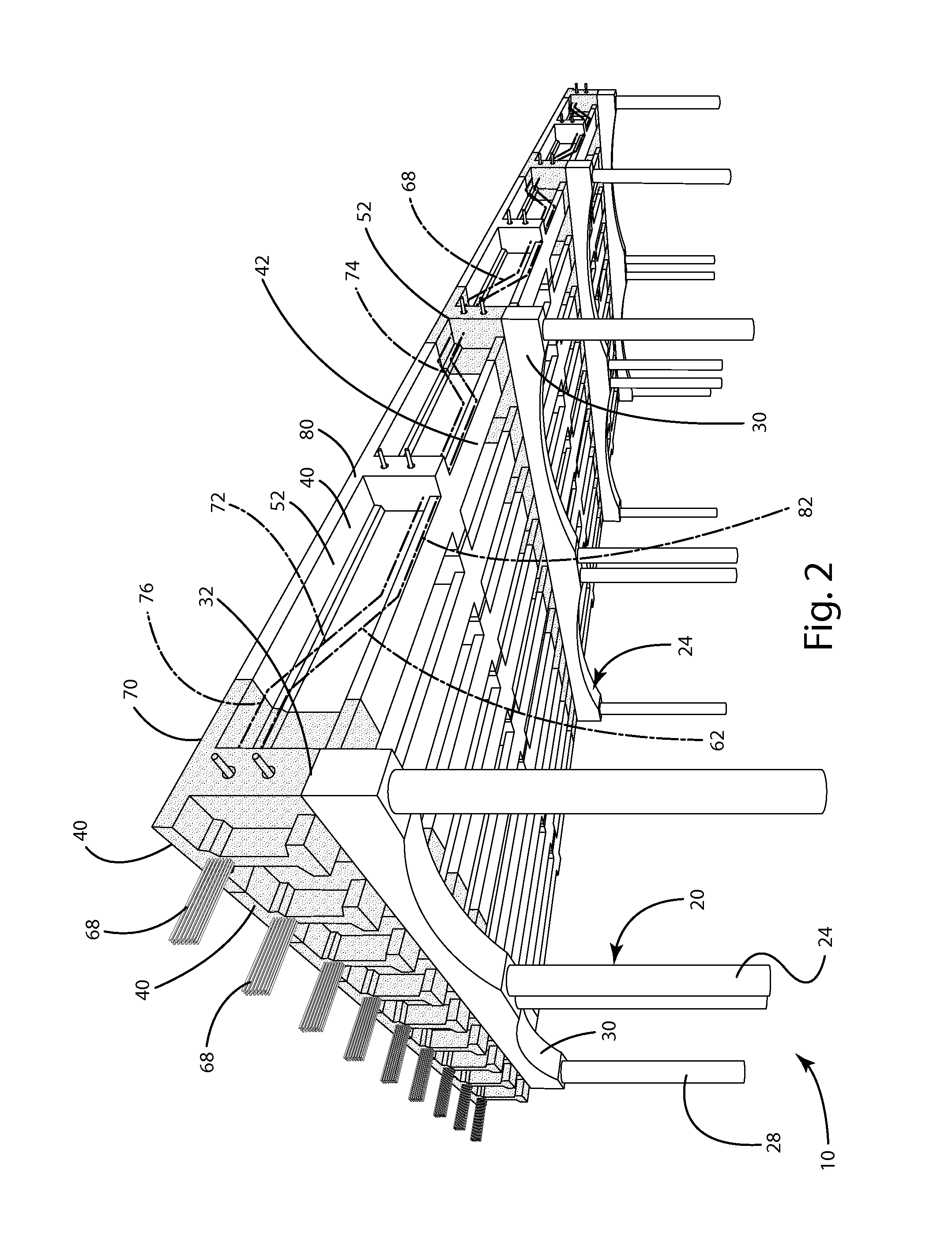
[0022]The present invention is directed to a bridge 10, generally illustrated in FIGS. 2 and 3. The bridge 10 is supported by a support structure 20 which supports longitudinal load members 40, also referred to as beams, which also form the deck 132 or traffic surface of the bridge 10. The bridge 10 is generally formed from concrete and pre-stressed through the use of a tensioning system 60, including internal tendons or tensioning members 68. As used in this application, the term pre-stressed or pre-tensioned refers to a bridge that uses tension created by tendons to increase strength and is formed from numerous adjacent pre-cast longitudinal load members 40.

[0023]As with all bridges, the bridge 10 of the present invention is supported by a support structure 20. While any support structure may be used, which vary widely in size shape and style, most bridges include an abutment (not shown) at each end for support. For concrete bridges of longer length, they may have...


PUM


Abstract

A pre-stressed concrete bridge using longitudinal load members of a single continuous beam including at least two types of concrete, one of which is ultra-high-performance concrete (UHPC) mix with a compressive strength exceeding 20 ksi and tensile strength exceeding 1.5 ksi in a region proximate to the support structure.

Description

CROSS REFERENCE TO RELATED APPLICATIONS[0001]This U.S. Patent Application claims the benefit of U.S. Provisional Patent Application Ser. No. 61 / 621,104, entitled “Continuous CFRP Decked Bulb T Beam Bridges For Accelerated Bridge Construction”, filed Apr. 6, 2012, the entire disclosure of the application being considered part of the disclosure of this application, and hereby incorporated by reference.BACKGROUND OF THE INVENTION[0002]The present invention is generally directed to a bridge and more particularly, to an improved pre-stressed, concrete bridge using longitudinal load members of a single continuous beam including at least two types of concrete, one of which is ultra-high-performance concrete (UHPC) mix with a compressive strength exceeding 20 ksi and tensile strength exceeding 1.5 ksi in a region proximate to the support structure.[0003]Engineers are consistently striving to build bridges that are stronger, lighter, and capable of spanning longer distances while having impr...

Claims


Application Information

Patent Timeline
Patent Type & Authority Applications(United States)
IPC IPC(8): E01D19/12
CPCE01D19/125E01D2/02E01D2101/28
Inventor GRACE, NABIL F.
Owner LAWRENCE TECHNOLOGICAL UNIV
Why Eureka
Try Eureka