Delay Mechanism of a Main Rod of a Gas Spring

Active Publication Date: 2013-10-17
AZOL GAS
View PDF4 Cites 9 Cited by
  • Summary
  • Abstract
  • Description
  • Claims
  • Application Information

AI Technical Summary

Benefits of technology

The patent is about a system that controls the speed of a withdrawal mechanism in a manufacturing process. This system allows for better control during the initial part of the withdrawal, which means parts can be produced faster. The system uses a throttle element to control the speed of the main rod as it moves through the first passage. This results in an increase in productivity, as more parts can be produced in a given amount of time. The patent is about improving this system to make it even more efficient and effective.

Problems solved by technology

The need to control the speed of the elements, tools and machines used to obtain the final part is becoming increasingly frequent among stamped part manufacturers, due to the increased complexity thereof.

Method used


Image

  • Delay Mechanism of a Main Rod of a Gas Spring
  • Delay Mechanism of a Main Rod of a Gas Spring

Examples


Embodiment Construction

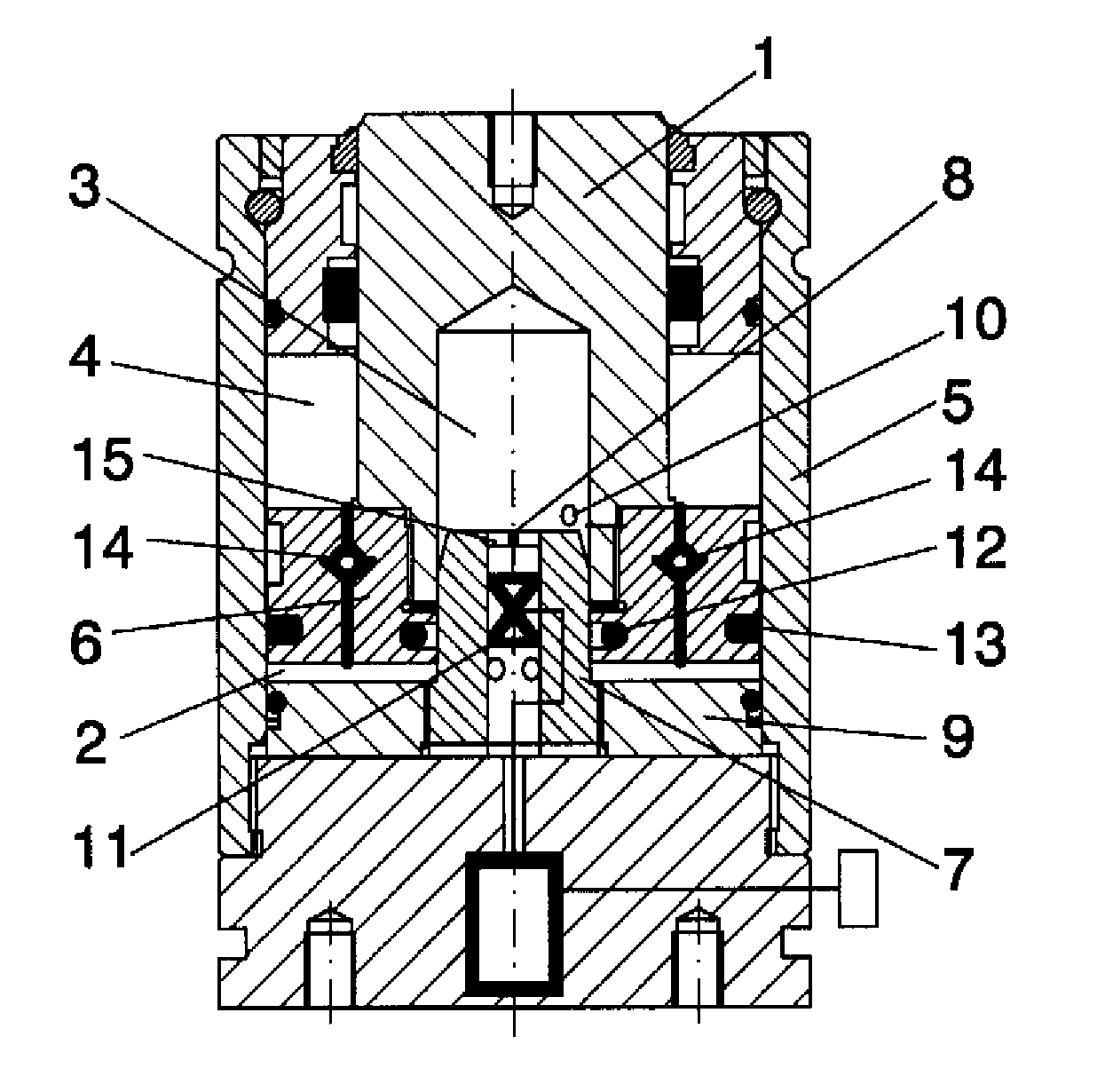
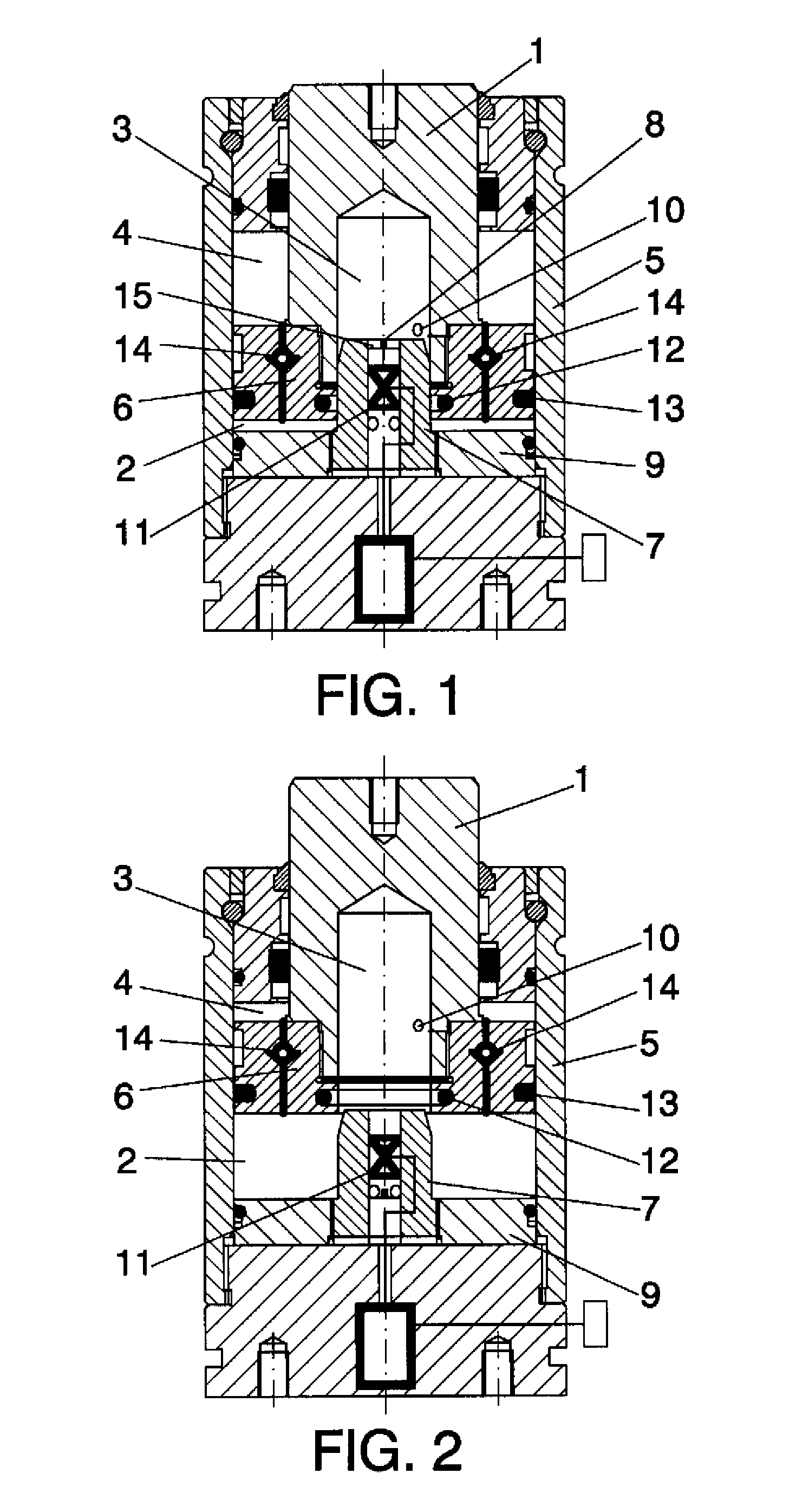
[0007]The variable speed delay system with withdrawal allows a delay control which is crucial in the first part of the withdrawal, as once part of the path travelled has been recovered it can return to the starting position more quickly, which would allow an increase in the number of parts to be produced within the same time period, i.e. an increase in productivity. The purpose of the invention is to allow said increase in productivity by ensuring that said rod does not return at constant speed, but rather ensuring that the final part of the withdrawal is faster.

[0008]The invention consists of fixing an inner rod to the base of the spring, having a height such that the closure gasket disposed inside the piston is only in contact with said inner rod along a travel path shorter than the travel path of the cylinder. A throttle element is disposed inside the hollow inner rod upon passage of the gas, the so-called first passage, wherein a gas shut-off valve controllable from the exterior...


PUM


Abstract

A delay mechanism of a main rod of a gas spring is described, having an inner rod and a series of gas chambers which are defined in the interior of the body of the spring in such a manner that, by controlling the passage of gas between said chambers, the speed and delay of the main rod of the spring is controlled.

Description

OBJECT OF THE INVENTION[0001]The present invention belongs to the field of stamping manufacturing systems.[0002]The object of the invention consists of a mechanism for increasing production and decreasing the time required to manufacture parts by means of stamping by controlling the working speed of the die elements.BACKGROUND OF THE INVENTION[0003]For some time now, gas springs have been used as an elastic force-limiting element in sheet metal stamping processes.[0004]Manufacturer requirements, both for producing more parts in the same amount of time and for producing more complex parts, have led to the control and increase of working speeds of all the die elements, including those of gas springs.[0005]The need to control the speed of the elements, tools and machines used to obtain the final part is becoming increasingly frequent among stamped part manufacturers, due to the increased complexity thereof. Advances in presses allow speeds at each point to be governed as required for e...

Claims


Application Information

Patent Timeline
IPC IPC(8): F16F9/02
CPCF16F9/02F16F9/0236F16F9/486
Inventor ESTIRADO VERA, FELIX JAVIERALEJOS PEREZ, OSCAR
Owner AZOL GAS
Why Eureka
Try Eureka