Programmable intelligent control method of and system for irrigation system

Inactive Publication Date: 2013-10-17
WOOD KEVIN JAMES
13 Cites 25 Cited by

AI-Extracted Technical Summary

Problems solved by technology

However, the operator may forget to cancel the watering cycle and th...

Method used

[0033]The timer controller 2 includes a user interface and a PLC that has a control program to control the operation of flow control devices, typically electromechanical valves/switches including but not limited to solenoid-actuated valves for irrigation systems in one or more watering or irrigation zones by sending electrical control signals to the corresponding electromechanical valves. Because the timer controller 2 contains memory so in the event of a complete power failure, the control program will not be lost. The timer controller 2 further comprises a LED or LCD 6 screen on the front, which displays total system information in multiple color tiles along with numerical, texts for quick and easy identification of all system functions as shown in FIG. 1.
[0049]Referring to FIGS. 5 and 6, the timer controller 2 has a plurality of electrical contact pins 11 on its back which are designed for electrically connecting to the electrical contact pins socket on the wiring back plate 5, which further has a plurality of port 12 designed for connecting to a plurality of valves/switches of the flow control devices to control the irrigat...

Benefits of technology

[0011]One object of the present invention is to provide a system for controlli...

Abstract

The present invention relates to an intelligent system for managing a plurality of flow control devices of the irrigation systems in one or multiple watering zones. In the preferred embodiment, the system of the present invention utilizes speech control technology known in the art to allow users to input operation commands directly into the controller or remotely through a remote control. The system further comprises a weather device which receives weather forecast information transmitted from wireless remote device and transmits said weather forecast to the controller as parameters to determine whether the preset watering cycle should be continued or suspended. The system further comprises flow sensor and will send alert message to user's mobile phone if the flow sensor detects excessive water flow. It will also send other text message to remind the user about water flow adjustment due to season changes and time for applying fertilizer.

Application Domain

Valve arrangementsWatering devices +5

Technology Topic

FertilizerSmart system +11

Image

  • Programmable intelligent control method of and system for irrigation system
  • Programmable intelligent control method of and system for irrigation system
  • Programmable intelligent control method of and system for irrigation system

Examples

  • Experimental program(1)

Example

[0031]The present invention relates generally to an intelligent control system used to manage the operation of flow control devices, typically solenoid-actuated valves and pump relays for irrigation systems such as sprinkler devices and other watering devices.
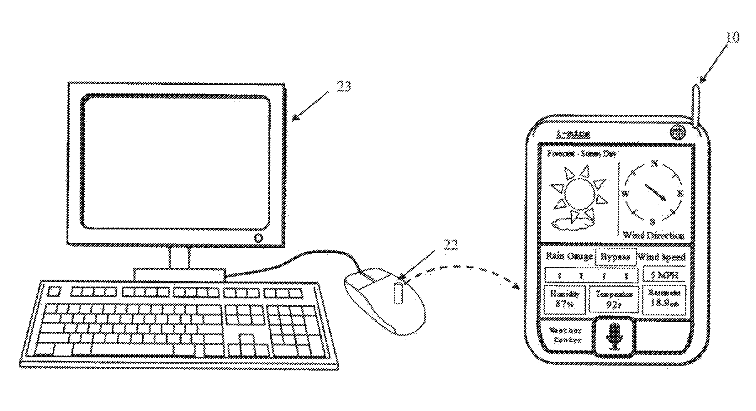
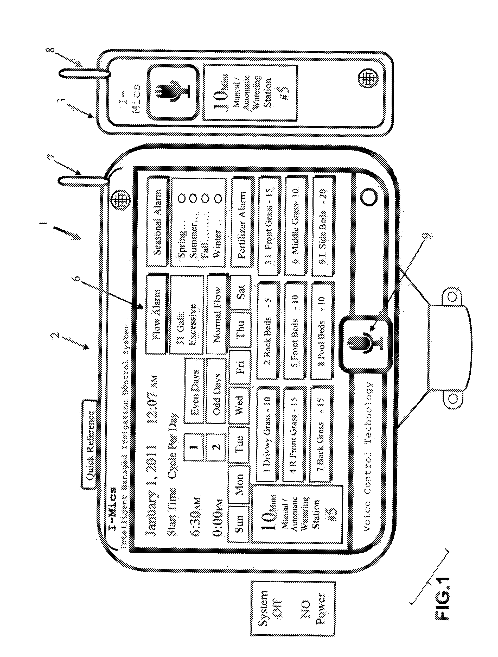
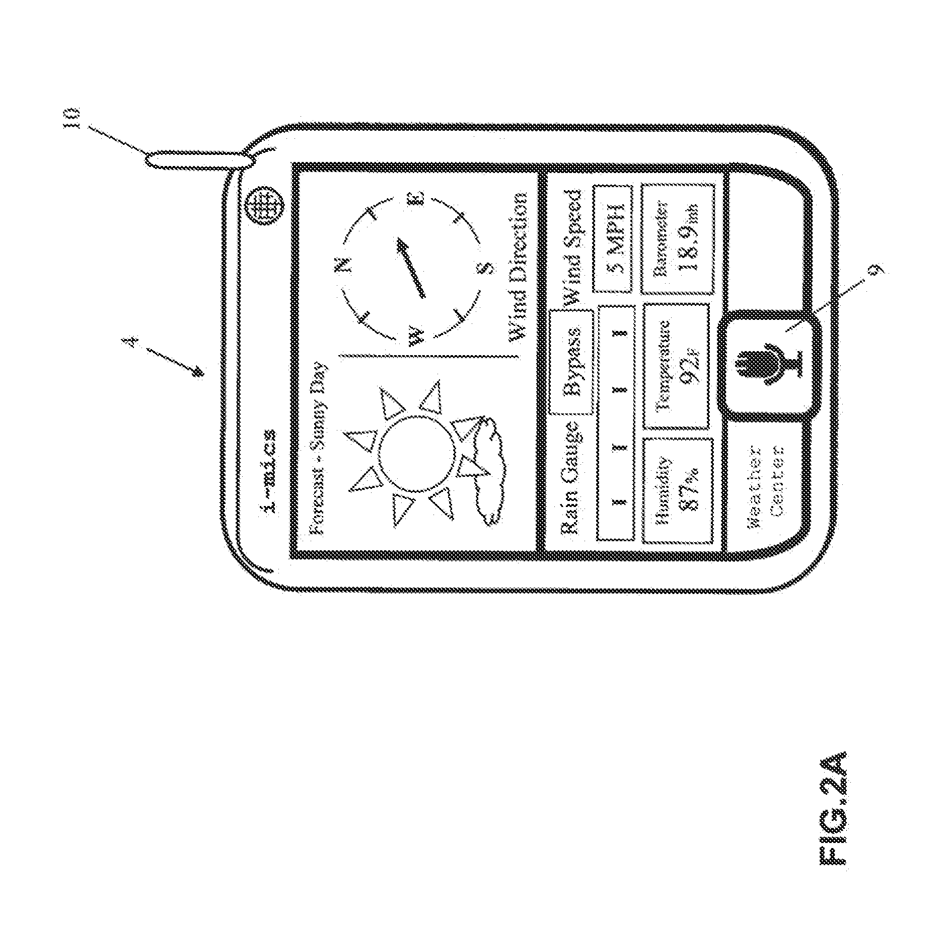
[0032]One of the embodiments of the intelligent control system 1 according to the present invention comprises a timer controller 2, a portable remote control 3, a weather device 4, and a wiring back plate 5. The timer controller 2 has a plurality of electrical contact pins on its back for electrically connecting to the wiring back plate 5 which has an electrical interface comprising a plurality of ports for connecting to a plurality of electromechanical valves/switches of irrigation system to control these irrigation system.
[0033]The timer controller 2 includes a user interface and a PLC that has a control program to control the operation of flow control devices, typically electromechanical valves/switches including but not limited to solenoid-actuated valves for irrigation systems in one or more watering or irrigation zones by sending electrical control signals to the corresponding electromechanical valves. Because the timer controller 2 contains memory so in the event of a complete power failure, the control program will not be lost. The timer controller 2 further comprises a LED or LCD 6 screen on the front, which displays total system information in multiple color tiles along with numerical, texts for quick and easy identification of all system functions as shown in FIG. 1.
[0034]The timer controller 2 may further comprise speech control technology known in the art to allow users to input operation commands.
[0035]In the preferred embodiment, the invention uses only “Speech Control Technology” to allow users to program all settings and operational functions. In another embodiment, the invention allows users to select pre-programmed operational functions by pushing buttons or touching icons. The timer controller 2 also comprises a radio frequency (RF) receiver antenna 7 which allows timer controller 2 to receive input from the remote control 3 from RF remote control antenna 8. A user may carry the RF remote control 3 separately which has a user interface and a RF transmitter and can transmit programming instructions and manual operation commands via RF transmission to the timer controller 2. This configuration allows the user to program the timer controller 2 remotely. In the preferred embodiment, both the timer controller 2 and the remote control 3 utilizes speech control technology known in the art to allow users to input operation command. The timer controller 2, remote control 3 and weather device 4 further comprise timing device so they can synchronize with each other.
[0036]Referring to FIG. 1, the LED or LCD screen 6 displays icons to show seasonal alarm, fertilizer alarm and flow alarm. The PLC can be programmed to give off three types of alarms: seasonal, fertilizer, and flow sensor. The alarms will beep and blink red at the time of watering adjustments (due to season changes), when a different fertilizer should be applied, and when excessive water flow is detected (which may be caused by broken sprinkler head, broken pipe or electrical fault in irrigation system). The system's app (e.g. “i-Mics app”) may be downloaded to a user's smart phone to receive from the system (i-Mics) 1 the weather data along with alarms and text messages informing the user the cause of the alarm. In one embodiment, the system 1 is programmed to send the user 2 cell phone text massages (at that time of alarm and 12 hours late) indicating that the alarm has gone off due to one or more of these factors: wind speed, rain forecast, time for fertilizer application, rain or excessive water flow. The flow sensor alarm will continue to blink red until the cause of alarm is repaired and canceled by user.
[0037]The system 1 utilizes speech control technology for user to program the timer controller 2. In the preferred embodiment, the user utilizes the speech control technology by first touching the “I-Mic button”9, after 1 flash and 1 beep sound; the user speaks command “SET” to program the timer controller. For example: [0038] “SET water days . . . Sunday, Tuesday, Thursday and Saturday” [0039] “SET start time 6:30 AM” [0040] “SET runtime 10 minutes station 5”
[0041]To get water usage information, the user can speak: [0042] “Water used last 30 days” [0043] “Average water used per day”
[0044]After each said commands, the timer will give off 2 beeps sound and 2 green flashes to confirm user's said commands and user's said command will be displayed on the screen.
[0045]The system 1 further comprises a built-in automatic motion sensor (not shown) to activate illumination of the screen for the timer controller 2, and weather device 4, said motion sensor will shut-off illuminated screen if no movement is detected within a pre-set time period, preferably 30 seconds.
[0046]Referring to FIG. 2A and FIG. 2B, there is disclosed a wireless weather device 4 that transmits weather forecast information such as wind speed/direction, rainfall amount, humidity, temperature and barometric readings through radio frequency (RF). The weather forecast information may be updated via the internet through a software program on a computer. As shown in FIG. 3, a USB transmitter 22 connected to the computer 23 will transmit the weather forecast information to the weather device 4 using radio frequency or other appropriate technology known in the art. The weather device 4 will then transmit the weather forecast to the time controller 2 using RF transmitter 10. The timer controller 2 will either stop watering or water based on the weather forecast data it receives.
[0047]The weather device 4 receives weather forecast that includes: barometric measurements, wind speed measurements, and rainfall measurements. The weather device 4 may be set via the iMics button 9 to tell the timer controller 2 to turn off the watering process when the forecasted rainfall measurements exceed a rain gauge limit. For example, the rain gauge limit may be set at ⅛ inch, ¼ inch, ½ inch, or 1 inch. If the forecast is sunny, the weather center 4 screen displays a sun indicating a normal condition (FIG. 2A). If the forecast is cloudy and rain, the weather center screen displays rain shut-off conditions (FIG. 2B). The weather center 4 will transmit the weather information and the operation commands to the timer controller 2 as parameters to further control the operation of the irrigation system as illustrated in in FIG. 4.
[0048]This unique feature of the present invention takes advantage of the modern weather forecast capability and wave the need of having to have additional temperature sensor or rain or humidity sensor that is utilized in other devices for irrigation control disclosed in the foregoing related art section. In another embodiment, the weather device 4 may be combined with the timer controller 2 as one unit.
[0049]Referring to FIGS. 5 and 6, the timer controller 2 has a plurality of electrical contact pins 11 on its back which are designed for electrically connecting to the electrical contact pins socket on the wiring back plate 5, which further has a plurality of port 12 designed for connecting to a plurality of valves/switches of the flow control devices to control the irrigation system. When the timer controller 2 is mounted onto the wiring back plate 5 via the mounting eyes 13 and the electrical contact pins 11 are inserted into the corresponding sockets 12, the timer controller 2 can control the corresponding valves/switches of the flow control device for the irrigation system. The wiring back plate 5 also comprises an electrical contact pin sockets 14 for the weather center 4 and an electrical contact pin socket 15 for the flow sensor (not shown). The flow data collected from the flow sensor may help timer controller 2 to determine whether there is excessive water flow which may be caused by broken sprinkler head or broken pipe or electrical fault in irrigation system and send alarm text messages to the user's mobile phone in time to alert the user and prevent further over-watering or flood.
[0050]In one embodiment, the system 1 is programmed to send the user 2 cell phone text massages (at that time of alarm and 12 hours late) indicating that the alarm has gone off due to one or more of these factors: wind speed, rain forecast, time for fertilizer application, rain or excessive water flow. The flow sensor alarm will continue to blink red until the cause of alarm is repaired and canceled by user.
[0051]The wiring back plate 5 is mounted in a fixed location. The wiring that connects to the flow control device (for example electromechanical valves for irrigation system) goes through the conduit bracket 17. There is a reset button 21 on the top of the timer controller 2 in this embodiment for resetting the timer controller to default settings.
[0052]The intelligent control system 1 of the present invention may further comprise a flow sensor which is a versatile remote transmitter capable of accurately measuring flow rates. The intelligent control system 1 may further comprise control device (electromechanical valves/pumps) for the irrigation system.
[0053]The method of or arrangement of wiring or connecting the above electronic components and mounting them will be well known to those with ordinary skill in the electronic and mechanical arts.
[0054]While there have been shown and described and pointed out the fundamental novel features of the invention as applied to the preferred embodiments, it will be understood that the foregoing is considered as illustrative only of the principles of the invention and not intended to be exhaustive or to limit the invention to the precise forms disclosed. Obvious modifications or variations are possible in light of the above teachings. The embodiments discussed were chosen and described to provide the best illustration of the principles of the invention and its practical application to enable one of ordinary skill in the art to utilize the invention in various embodiments and with various modifications as are suited to the particular use contemplated All such modifications and variations are within the scope of the invention as determined by the appended claims when interpreted in accordance with the breadth to which they are entitled.

PUM

no PUM

Description & Claims & Application Information

We can also present the details of the Description, Claims and Application information to help users get a comprehensive understanding of the technical details of the patent, such as background art, summary of invention, brief description of drawings, description of embodiments, and other original content. On the other hand, users can also determine the specific scope of protection of the technology through the list of claims; as well as understand the changes in the life cycle of the technology with the presentation of the patent timeline. Login to view more.
Why Eureka
Try Eureka