Steam-to-gas heat exchanger

a heat exchanger and steam technology, applied in the field of heat exchangers, can solve the problems of reducing the efficiency of the heat exchanger, affecting the safety of users, and affecting the safety of users, and achieve the effect of minimizing thermal stresses

Inactive Publication Date: 2013-10-17
FETCU DUMITRU
View PDF4 Cites 11 Cited by
  • Summary
  • Abstract
  • Description
  • Claims
  • Application Information

AI Technical Summary

Benefits of technology

[0011]The distributed inlet ensures a uniform cooling of the portion of the heat pipes within the first chamber and thus a uniform extraction of heat from the heat pipes. The distributed inlet minimizes any localized heating within the first chamber, which is typically associated with a localized inlet for the water.
[0018]The first and second heat exchanging chambers are preferably separated by a separation plate. The plurality of heat pipes are preferably supported within the heat exchanger by the separation plate which is coupled to the heat pipes at a position intermediate opposite ends of the heat pipes. Accordingly, the separation plate obviates the requirement to support the heat pipes at their free end and as such the free ends of the heat pipes can be left uncoupled. This therefore enables the heat pipes to expand and contract along their length during use thereby minimizing thermal stresses upon the heat pipes.

Problems solved by technology

It is found however that the heat extracted from the heat pipes within the chamber varies between heat pipes which can thus reduce the efficiency of the heat exchanger and cause an early failure of one or more of the heat pipes.
Moreover, it is found that the variation in heat extraction between heat pipes can lead to a dangerous build up of heat within the heat exchanger.

Method used


Image

  • Steam-to-gas heat exchanger
  • Steam-to-gas heat exchanger
  • Steam-to-gas heat exchanger

Examples


Embodiment Construction

[0026]The present invention will now be described in detail with reference to several embodiments thereof as illustrated in the accompanying drawings. In the following description, numerous specific details are set forth in order to provide a thorough understanding of embodiments of the present invention. It will be apparent, however, to one skilled in the art, that embodiments may be practiced without some or all of these specific details. In other instances, well known process steps and / or structures have not been described in detail in order to not unnecessarily obscure the present invention. The features and advantages of embodiments may be better understood with reference to the drawings and discussions that follow.

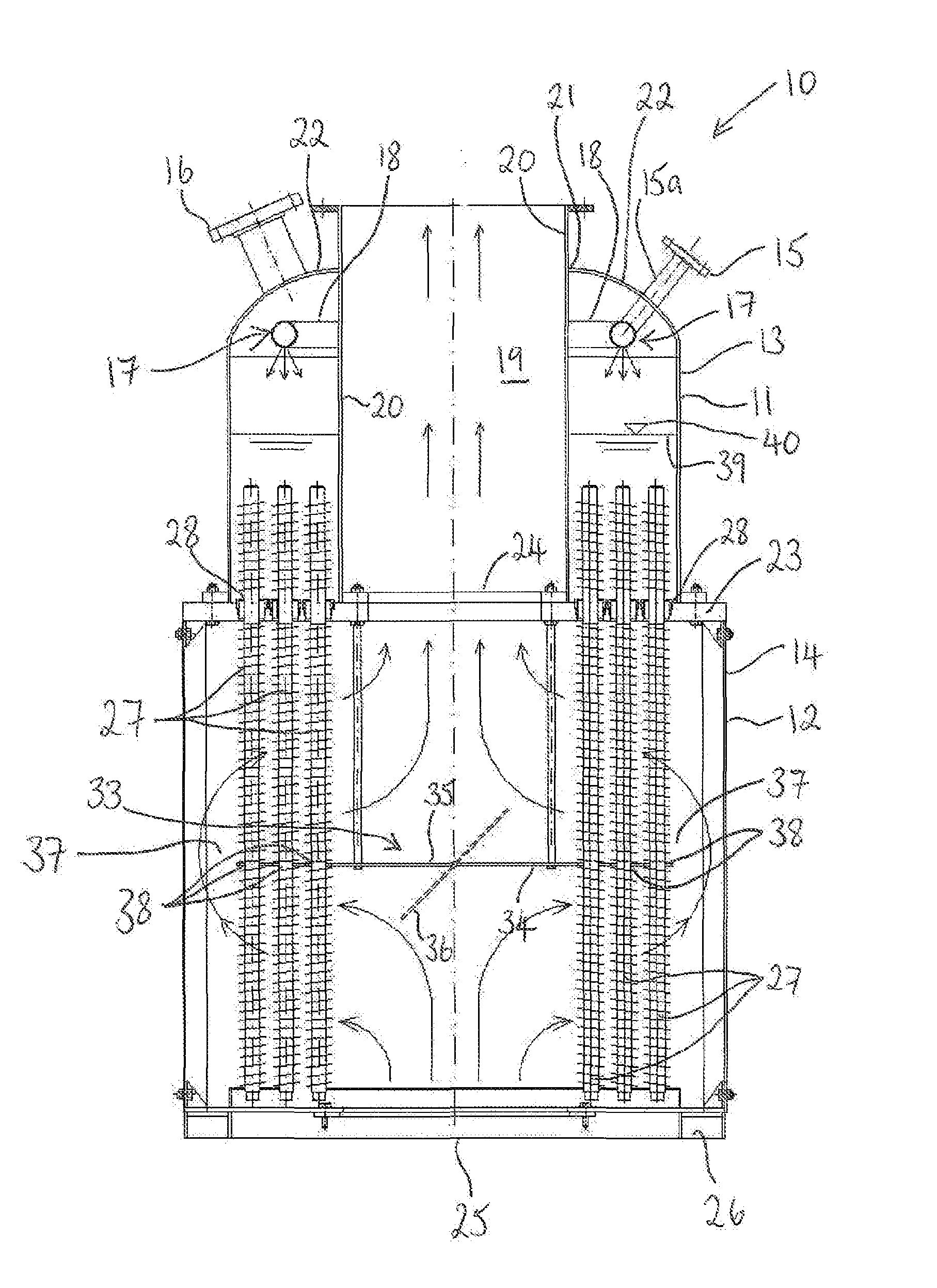
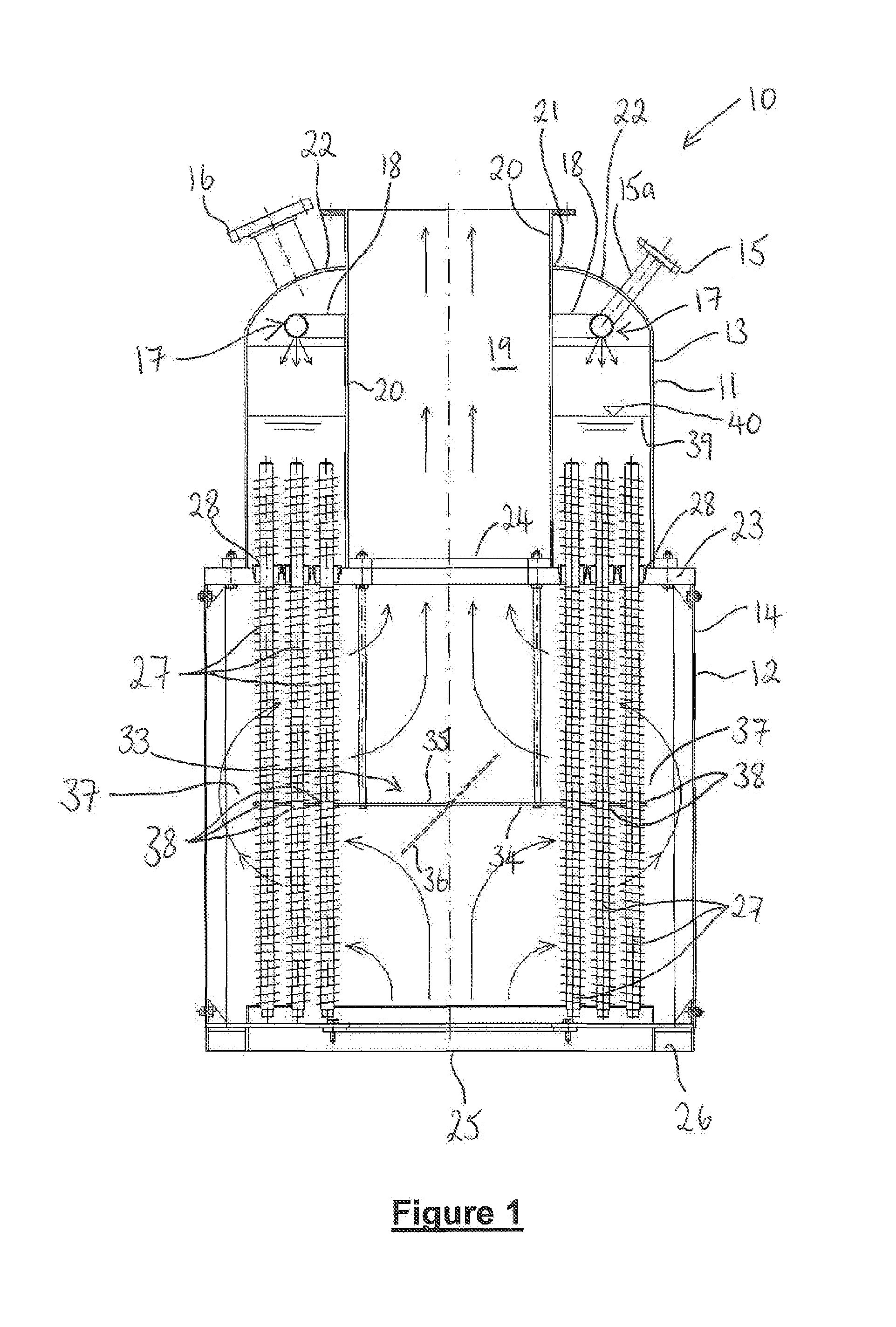
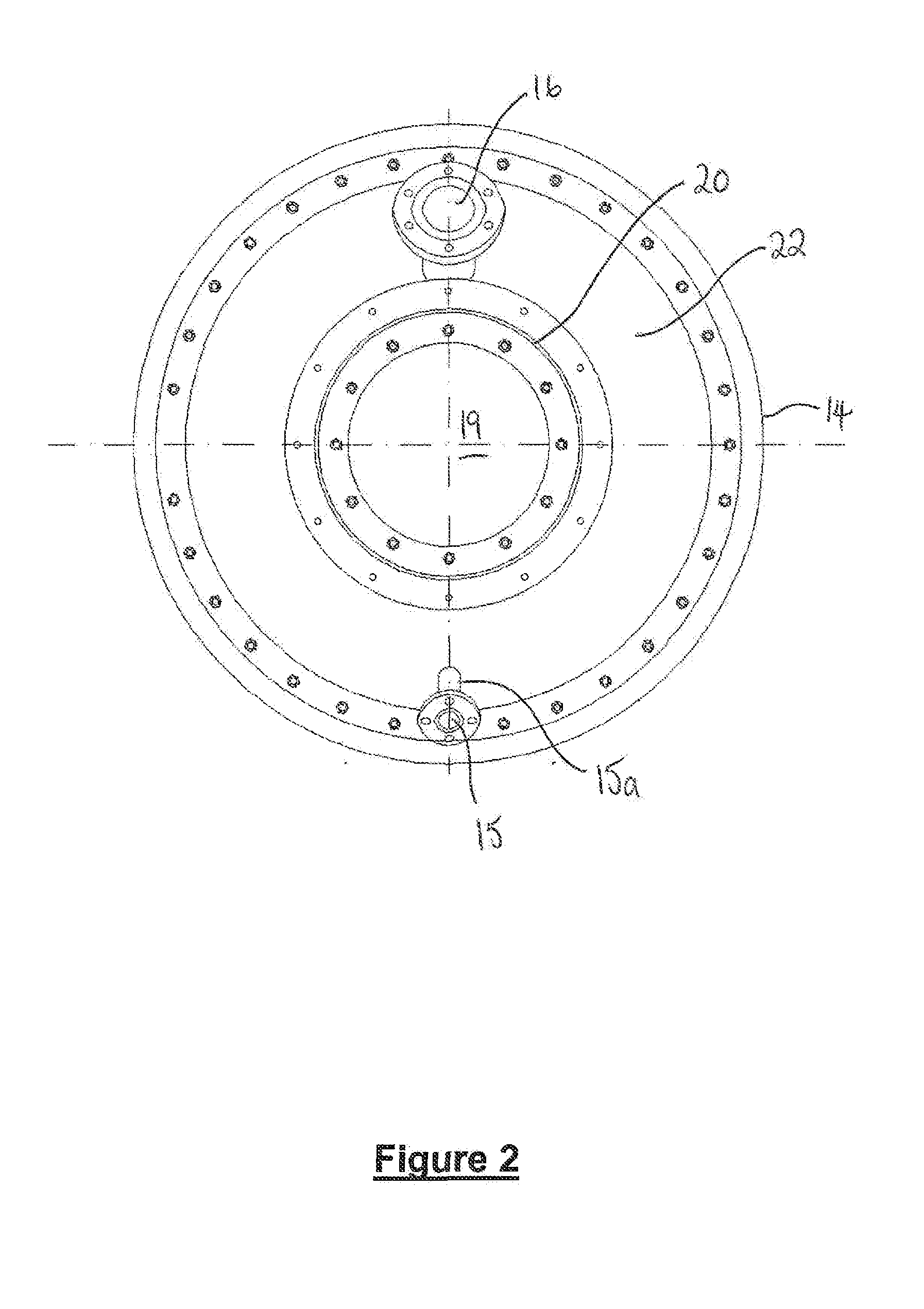
[0027]Referring to FIGS. 1 to 3 of the drawings, there is illustrated a heat exchanger 10 according to an embodiment of the present invention for generating steam from water. The heat exchanger 10 comprises a first heat exchanging chamber 11 and a second heat exchang...


PUM


Abstract

A heat exchanger for generating steam from water is disclosed. The exchanger comprises a first heat exchanging chamber, a second heat exchanging chamber and an array of heat pipes which are arranged to extend from within the first heat exchanging chamber to within the second heat exchanging chamber. The first heat exchanging chamber comprises a distributed inlet for passing the water into the first chamber from a distributed position around the chamber and an outlet through which the steam can exit the first chamber, the water being arranged to pass over the portion of the heat pipes which extend within the first chamber. The second heat exchanging chamber comprises an inlet for receiving a gas into the chamber and an outlet through which the gas can exit the second chamber, the gas being arranged to pass over the portion of the heat pipes which extend within the second chamber.

Description

CROSS REFERENCE TO RELATED APPLICATIONS [0001]This non-provisional application claims the benefit of provisional application No. 61 / 612,254 filed on Mar. 17, 2012, entitled “Steam-to-Gas Heat Exchanger”, including Appendix A, which application and appendix are incorporated herein in their entirety by this reference.BACKGROUND [0002]The present invention relates to a heat exchanger and particularly, but not exclusively to a heat exchanger comprising heat pipes.[0003]A heat pipe is a hermetically sealed evacuated tube typically comprising a mesh or sintered powder wick and a working fluid in both the liquid and vapor phase. When one end of the tube is heated the liquid turns to vapor upon absorbing the latent heat of vaporization. The hot vapor subsequently passes to the cooler end of the tube where it condenses and gives out the latent heat to the tube. The condensed liquid then flows back to the hot end of the tube and the vaporization-condensation cycle repeats. Since the latent he...

Claims


Application Information

Patent Timeline
Patent Type & Authority Applications(United States)
IPC IPC(8): F28D15/02
CPCF28D15/02F28F9/22F28F27/02F28D15/0275F28F1/36F28D21/001F22B1/165
Inventor FETCU, DUMITRU
Owner FETCU DUMITRU
Why Eureka
Try Eureka