
Ultraviolet-Based Sterilization

a technology of ultraviolet light and sterilization chamber, applied in the field of ultraviolet light-based sterilization, can solve the problems of serious limitations on applications, mercury lamps are fragile and bulky, and mercury lamps have significant drawbacks

Active Publication Date: 2013-10-17
SENSOR ELECTRONICS TECH
View PDF24 Cites 60 Cited by
  • Summary
  • Abstract
  • Description
  • Claims
  • Application Information

AI Technical Summary

Benefits of technology

The invention provides a system for sterilizing objects using ultraviolet radiation. The system includes a set of ultraviolet radiation sources and a set of wave guiding structures that direct the ultraviolet radiation to specific surfaces on the object. The wave guiding structures can include an ultraviolet reflective surface with a high ultraviolet reflection coefficient. The computer system operates the ultraviolet radiation sources to deliver a target dose of ultraviolet radiation to the object surfaces. The system can also include an ultrasonic unit for removing debris from the object surfaces before delivering the ultraviolet radiation. The technical effects include efficient and effective sterilization of objects using ultraviolet radiation.

Problems solved by technology

However, the use of mercury lamps has significant drawbacks.
For example, mercury lamps are fragile and bulky and mercury is an extremely dangerous element, which implies serious limitations on applications of the mercury-based water purification systems.
In particular, mercury lamps are not practical for use in transport and individual systems.
An additional limitation is an inability to adjust or control a radiation spectrum of the mercury lamp.
To this extent, the peaks of a mercury lamp do not exactly coincide with the absorption peaks of DNA and proteins, thereby decreasing the sterilization efficiency.
Nevertheless, the need for contact and even steering the sterilizing water with a fragile quartz sleeve with the mercury lamp inside makes the device dangerous for residential applications and not appropriate for transport, field, and portable applications.

Method used


Image

  • Ultraviolet-Based Sterilization
  • Ultraviolet-Based Sterilization
  • Ultraviolet-Based Sterilization

Examples


Embodiment Construction

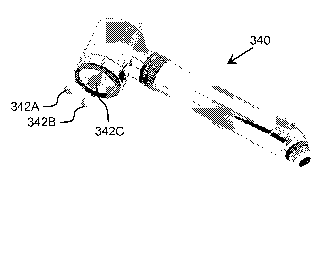
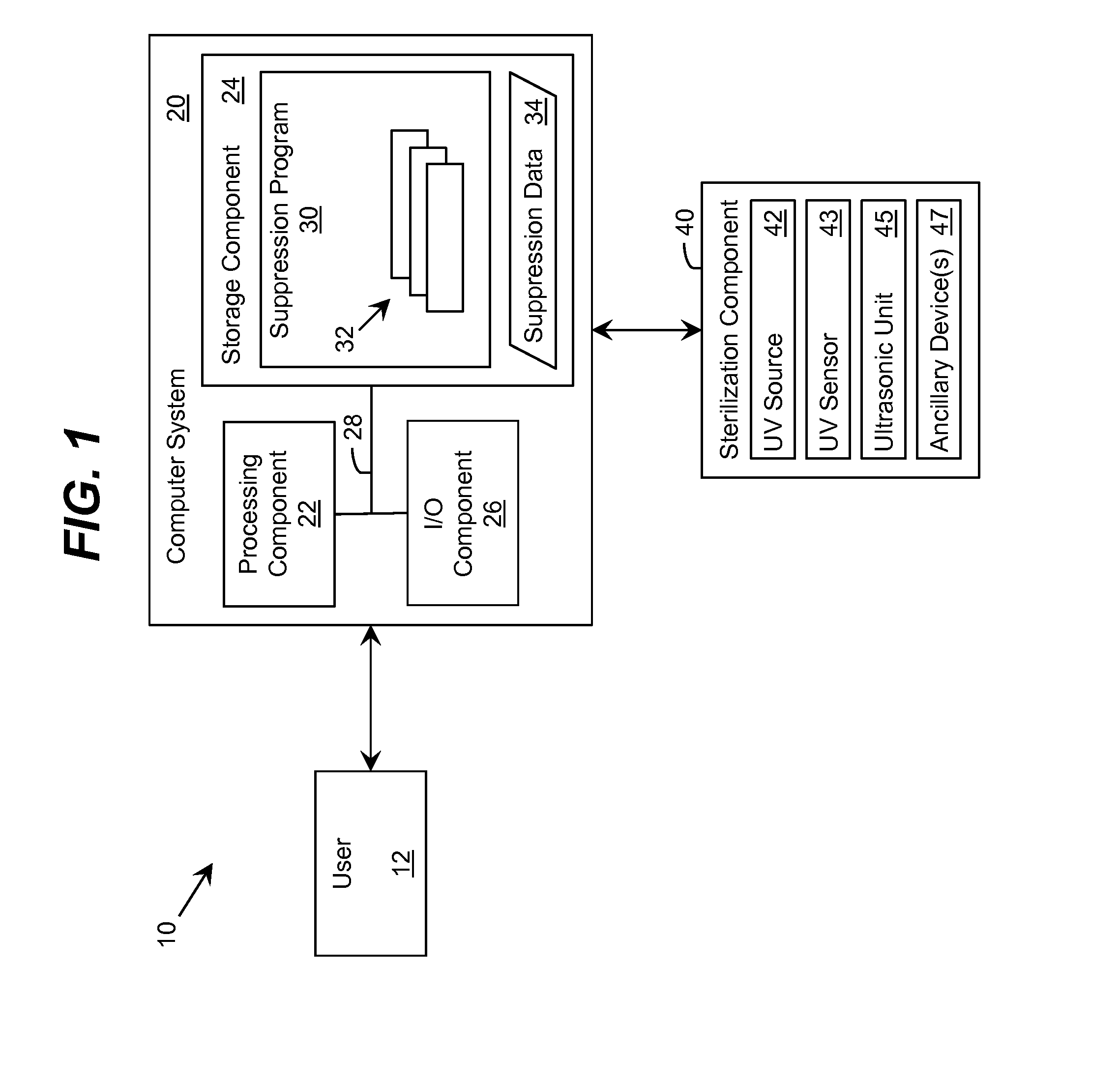
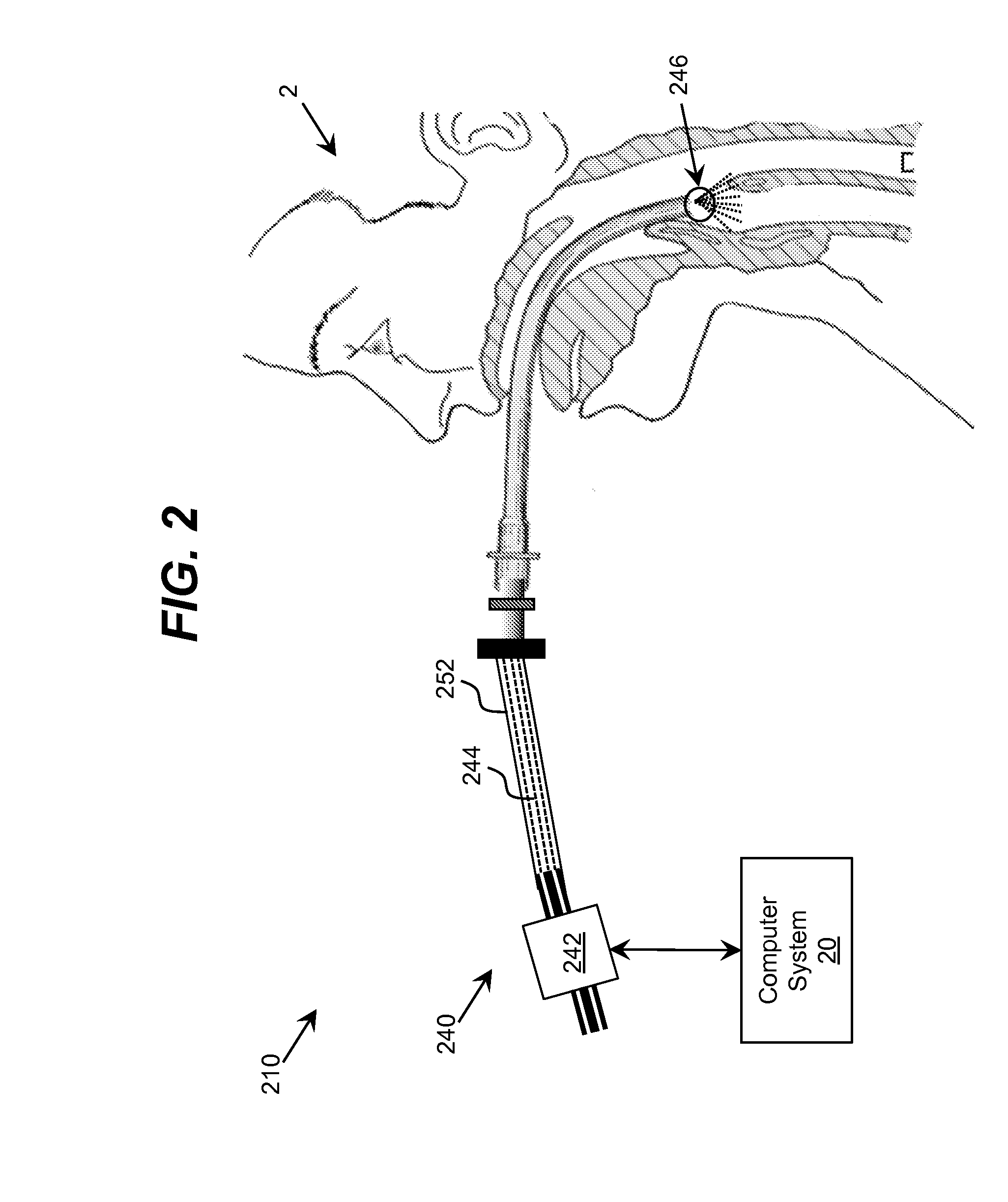
[0021]As indicated above, aspects of the invention provide a system for sterilizing at least one surface of an object. The system includes a set of ultraviolet radiation sources and a set of wave guiding structures configured to direct ultraviolet radiation having a set of target attributes to a desired location on at least one surface of the object. The set of wave guiding structures can include at least one ultraviolet reflective surface having an ultraviolet reflection coefficient of at least thirty percent. Furthermore, the system can include a computer system for operating the ultraviolet radiation sources to deliver a target dose of ultraviolet radiation to the at least one target surface of the object.

[0022]A solution described herein can provide a safer design (e.g., mercury lamps do not need to be used in field, transport, and / or portable embodiments), a longer operating lifetime (e.g., ultraviolet light emitting diodes can have a longer operating life than a typical mercur...


PUM

PropertyMeasurementUnit
wavelengthsaaaaaaaaaa
first ultraviolet wavelengthaaaaaaaaaa

Abstract

A system for sterilizing at least one surface of an object is provided. The system includes a set of ultraviolet radiation sources and a set of wave guiding structures configured to direct ultraviolet radiation having a set of target attributes to a desired location on at least one surface of the object. The set of wave guiding structures can include at least one ultraviolet reflective surface having an ultraviolet reflection coefficient of at least thirty percent. Furthermore, the system can include a computer system for operating the ultraviolet radiation sources to deliver a target dose of ultraviolet radiation to the at least one target surface of the object.

Description

REFERENCE TO RELATED APPLICATIONS[0001]The current application claims the benefit of co-pending U.S. Provisional Application No. 61 / 624,395, titled “UV LED Sterilization System,” which was filed on 16 Apr. 2012, and which is hereby incorporated by reference.TECHNICAL FIELD[0002]The disclosure relates generally to ultraviolet-based sterilization, and more particularly, to an improved solution for sterilizing a surface using ultraviolet radiation.BACKGROUND ART[0003]Ultraviolet water and air purification and sterilization systems are known and have a successful history of development. The main unit of these ultraviolet systems is a source of ultraviolet radiation having wavelength(s) close to the absorption peaks of biologically significant molecules of DNA and proteins. The system can sterilize a medium to a safe condition providing the power of the ultraviolet source and an exposure time are sufficient to destroy the internal biomolecular structure of bacteria, viruses, protozoa and...

Claims


Application Information

Patent Timeline
Patent Type & Authority Applications(United States)
IPC IPC(8): A61L2/10
CPCA61L2/10A61N5/0601A61L2/0047A61N5/0624A61N2005/0609A61N2005/0651A61N2005/0661
Inventor GASKA, REMIGIJUSSHUR, MICHAELDOBRINSKY, ALEXANDERBETTLES, TIMOTHY JAMESSHATALOV, MAXIM S.
Owner SENSOR ELECTRONICS TECH
Learn More