Smart ac panel

Inactive Publication Date: 2013-10-17
MAKANAWALA TEJESH C
View PDF0 Cites 5 Cited by
  • Summary
  • Abstract
  • Description
  • Claims
  • Application Information

AI Technical Summary

Benefits of technology

[0009]It is another object of the invention to control every outlet powered device in the home.
[0010]Smart AC Panel replaces the existing AC Panel in a home. It not only includes existing AC Panel function such as bus bar and circuit breakers, but also current sensor, voltage sensing circuitry and relay devic

Problems solved by technology

Due to the added cost of each module, generally many of the outlets are skipped.
The

Method used


Image

  • Smart ac panel
  • Smart ac panel
  • Smart ac panel

Examples


Embodiment Construction

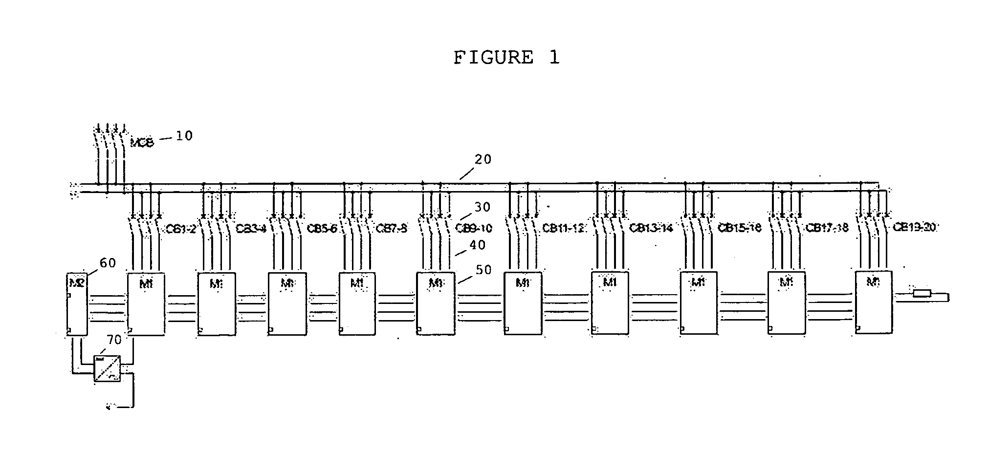
[0015]FIG. 1 is a schematic view of a Smart AC panel internally. It shows the Main Circuit Breaker (MCB) 10 on top connected to the Busbar 20. Branch Circuit Breaker (CBx) 30 is shown as 4 breakers, though in general they are 1 or 2. L1 and L2 go to first and second circuit of a 2 pole breaker. Wires 40 in a standard AC panel leave the panel, but in a Smart AC Panel, they connect to the M1PCB 50. The external wires 40 are connected via ConnectionPoint 100. The M1PCB 50 and M2PCB 60 are powered with +5 VDC 94 from the DCpowersupply 70. Common GND 92 is used.

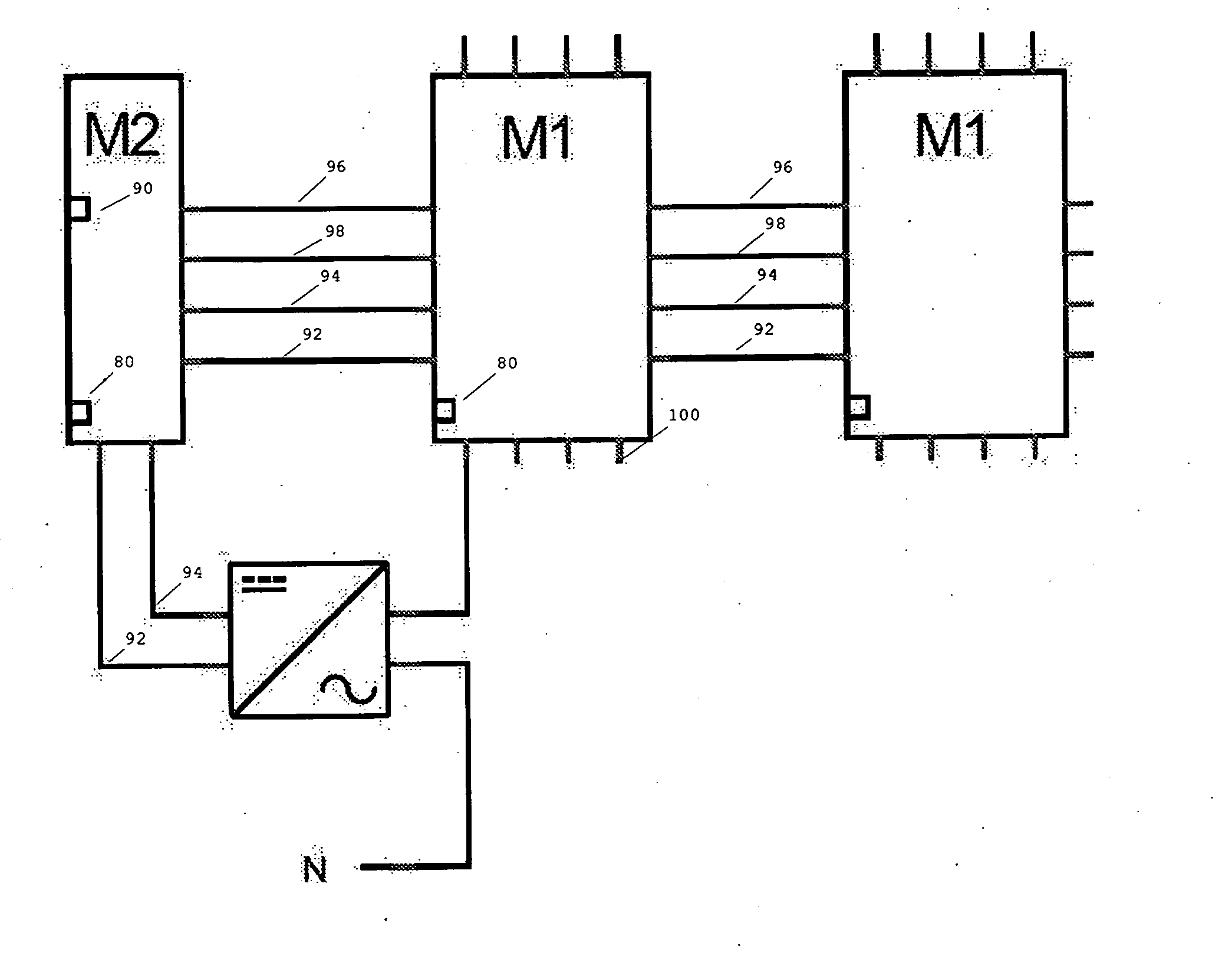
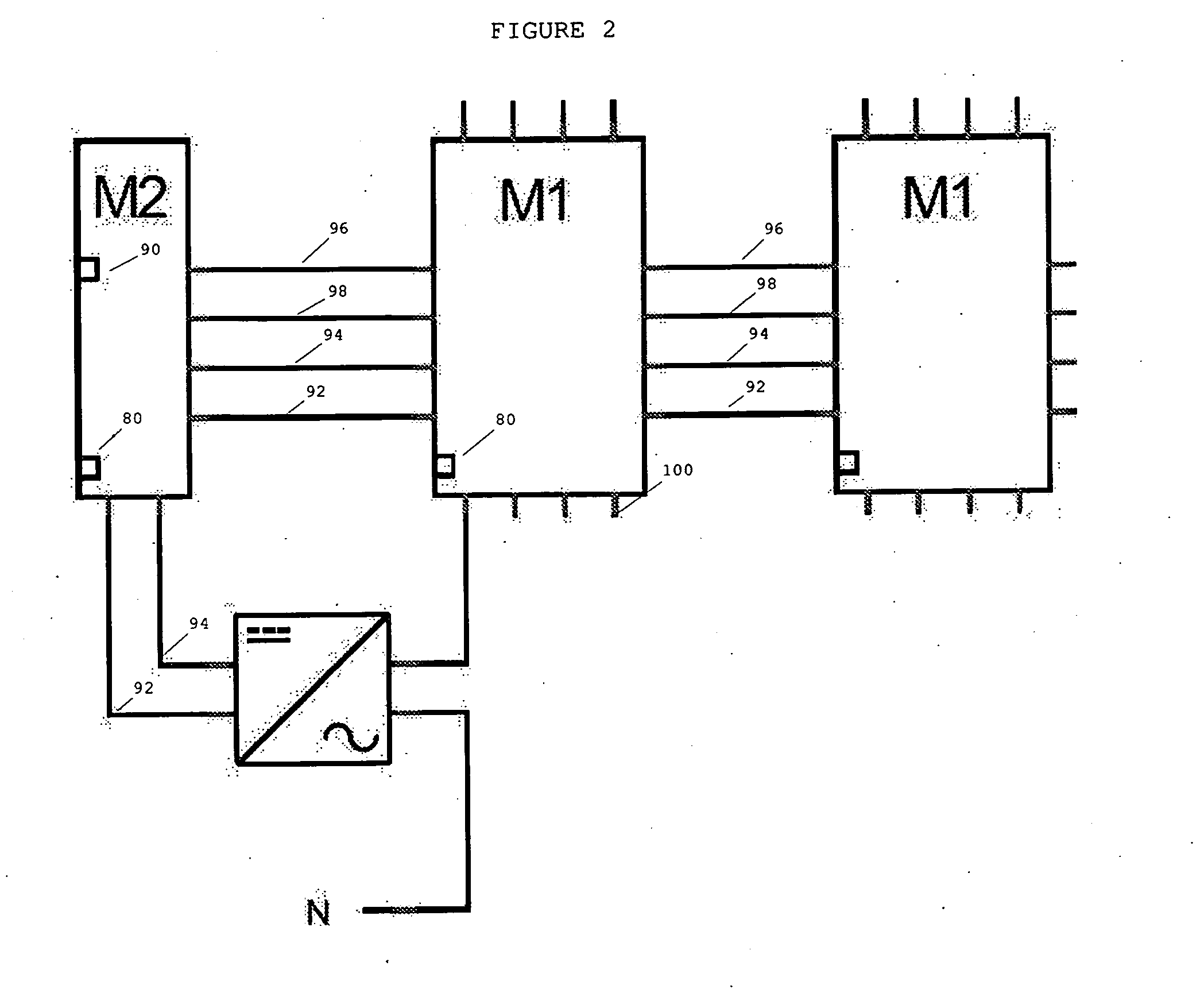
[0016]FIG. 2 is a schematic view of a Smart AC panel focusses on the interfaces between M1PCB 50 and M2PCB 60, and how they are integrated with rest of the system. M1PCB 50 has CAN-High 96 and CAN-Low 98 interface to communicate with M2PCB 60. Both M1PCB 50 and M2PCB 60 have a Debugport 80 for software debugging. Ethernetport 90 in included in the M2PCB 60 to provide internet / web connectivity.

[0017]Since other modifications and ch...


PUM


Abstract

Smart AC Panel replaces the existing AC Panel in a home. It not only includes existing AC Panel function such as bus bar and circuit breakers, but also current sensor, voltage sensing circuitry and relay devices to help control and monitor power associated with each branch circuit. The current sensor, voltage sensing circuitry interfaces to an embedded controller. Various embedded controllers are connected through CAN serial communication to a supervisory embedded controller which in turn has internet connectivity.

Description

RELATED APPLICATIONS[0001]The present application is a continuation-in-part application of United States provisional patent application, Ser. No. 61 / 376,269, filed Aug. 24, 2010, for SMART AC PANEL, by TEJESH MAKANAWALA, included by reference herein and for which benefit of the priority date is hereby claimed.FIELD OF THE INVENTION[0002]The present invention relates to AC panels in homes and, more particularly, to adding smartness and internet connectivity to these AC panels.BACKGROUND OF THE INVENTION[0003]As the world heads towards reduced energy consumption and lower energy costs, green technology products for homes are being constantly released to the market. In order to better understand what products need replacement, one needs to better understand what energy it is consuming. It would also be useful to experiment with reducing energy consumption of existing devices by programmatically enabling and disabling the device.[0004]The most common solutions for this problem is distri...

Claims


Application Information

Patent Timeline
IPC IPC(8): G01R21/06
CPCG01R21/06Y04S10/30G01R22/063G05B15/02Y04S40/128H02J13/00002H02J13/00028Y02E60/00Y04S20/00Y02B90/20
Inventor MAKANAWALA, TEJESH C
Owner MAKANAWALA TEJESH C
Why Eureka
Try Eureka