Flat panel x-ray source

a flat panel x-ray source and x-ray technology, applied in the field of x-ray radiation, can solve the problems of low power efficiency of x-ray tubes, cathode x-ray tubes sharing limitations, and the production of x-rays by the electron beam striking the target also generates a considerable amount of heat, so as to achieve high power levels, improve heat dissipation, and efficient source of x-ray flux generation

Inactive Publication Date: 2013-10-17
STELLARRAY
View PDF2 Cites 12 Cited by
  • Summary
  • Abstract
  • Description
  • Claims
  • Application Information

AI Technical Summary

Benefits of technology

[0017]An advantage of the invention is the generation of X-ray flux from a wider area than is possible with point sources and at higher energies than are possible with thin-film X-ray targets formed on the exit window. A specific advantage is that the invention can be used to make a flat, wide-area X-ray source that can enable more compact equipment for X-ray imaging, lithography or medical therapy than is the case with conventional X-ray tubes, which require a throw distance for the flux to cover a wide area. As a further specific advantage, the invention can be used to make X-ray sources which are long, thin and flat, thereby enabling the construction of more compact computed tomography apparatus.
[0018]Another advantage of the invention is the efficient generation of X-ray flux. This allows the construction of apparatus using X-ray flux to be more power efficient or more compact for a given level of rated power output.
[0019]A further advantage of the invention is improved heat dissipation from the wide X-ray target, which can be made of a sheet or slab of metal with the other side from the target exposed to atmosphere or connected to a heat sinking structure exposed to atmosphere. Improved heat dissipation means that the source can generate more X-ray flux for longer periods of time, which is useful in applications such as biohazard decontamination. The radiation source built according to the invention will also require less cooling than conventional sources. For example, forced air cooling can be used for radiation sources built according to the invention at power output levels which would require water cooling in conventional sources.
[0020]Another advantage of the invention is that it can be used as a wide, pixelated source of X-ray flux. This pixelated X-ray flux source may be used in conjunction with pixelated X-ray detectors to construct a compact radiation imaging apparatus. A specific advantage of such an apparatus in medical imaging is that the flux source can be addressed to emit radiation only in those areas where a radiation image is needed, thereby reducing the total amount of radiation directed at human or other imaging subjects.
[0021]A further advantage of the invention when used to produce X-ray flux is that it can increase the throughput of sterilization or decontamination processes.BRIEF SUMMARY OF THE INVENTION
[0022]The invention disclosed herein provides a radiation source which can emit X-ray flux and other forms of radiation producible by an electron beam current. The substance of the invention is the formation of the cathode or cathode array which produces the electron beam current on the window through which the radiation will exit the source. The cathodes in the array have space between them so as to provide open area on the window. The radiation source disclosed herein can be made in formats which are compact or flat as compared with prior art radiation sources. It can be used to produce X-ray flux over wide areas for such purposes as radiation imaging, sterilization, decontamination of biohazards or photolithography.BRIEF DESCRIPTION OF THE FIGURES

Problems solved by technology

X-ray tubes commonly have low power efficiencies; typically only about 1% of the power used to produce the electron beam current is realized in the X-ray beam energy exiting the tube.
The production of X-rays by the electron beam striking the target also generates a considerable amount of heat, since most of the beam energy is absorbed in the target.
While they offer several improvements, these cold cathode X-ray tubes share the limitations of their hot filament tube predecessors in being essentially point sources of X-rays.
A limitation of this type of X-ray source is that the heat produced in this process can be difficult to manage.
In doing so, thermal stresses will be produced which necessarily limit the power of the X-rays that can be generated in this manner.
Chemical and gas methods for the remediation of hazards such as anthrax, ricin, or smallpox suffer a number of limitations, including hazards to human operators during their application, lingering hazards after they have been applied, limited effectiveness, long set-up and application times and destruction of electronic and other equipment in the treatment area.

Method used


Image

  • Flat panel x-ray source
  • Flat panel x-ray source
  • Flat panel x-ray source

Examples


Embodiment Construction

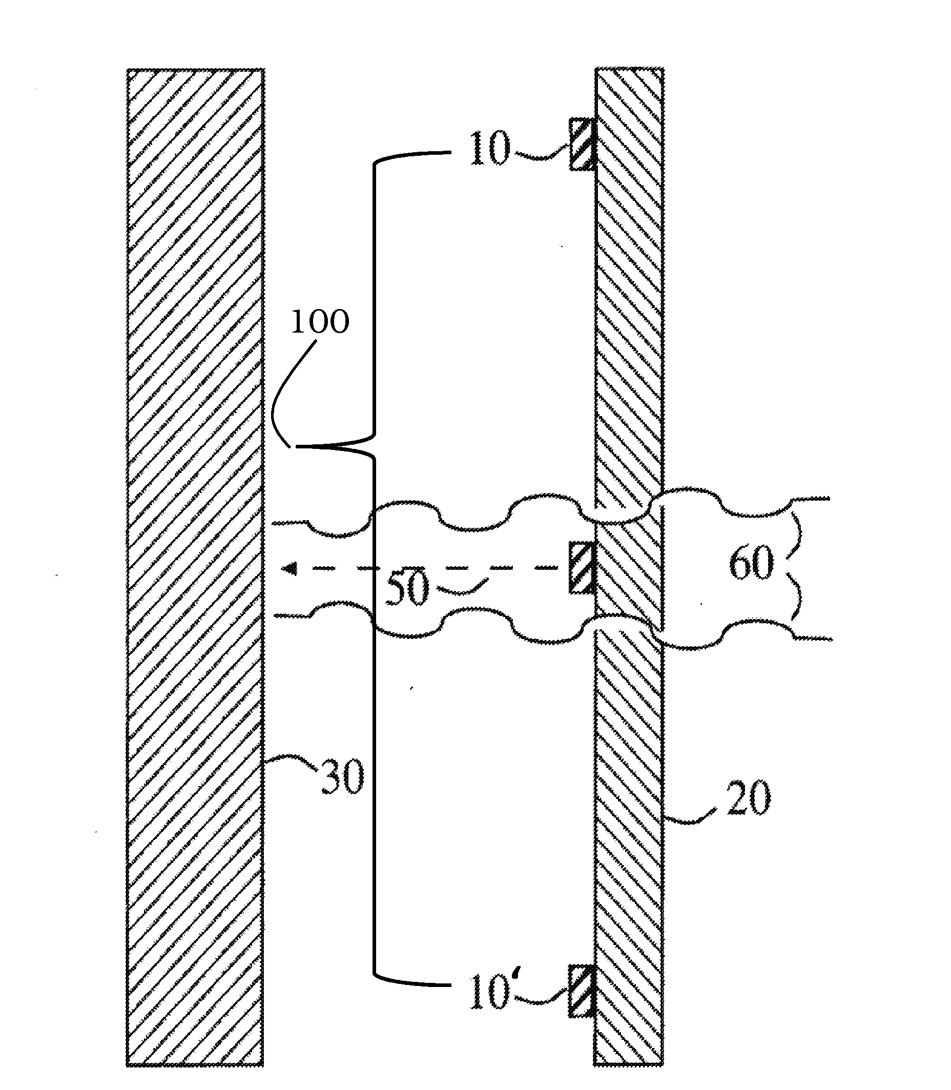
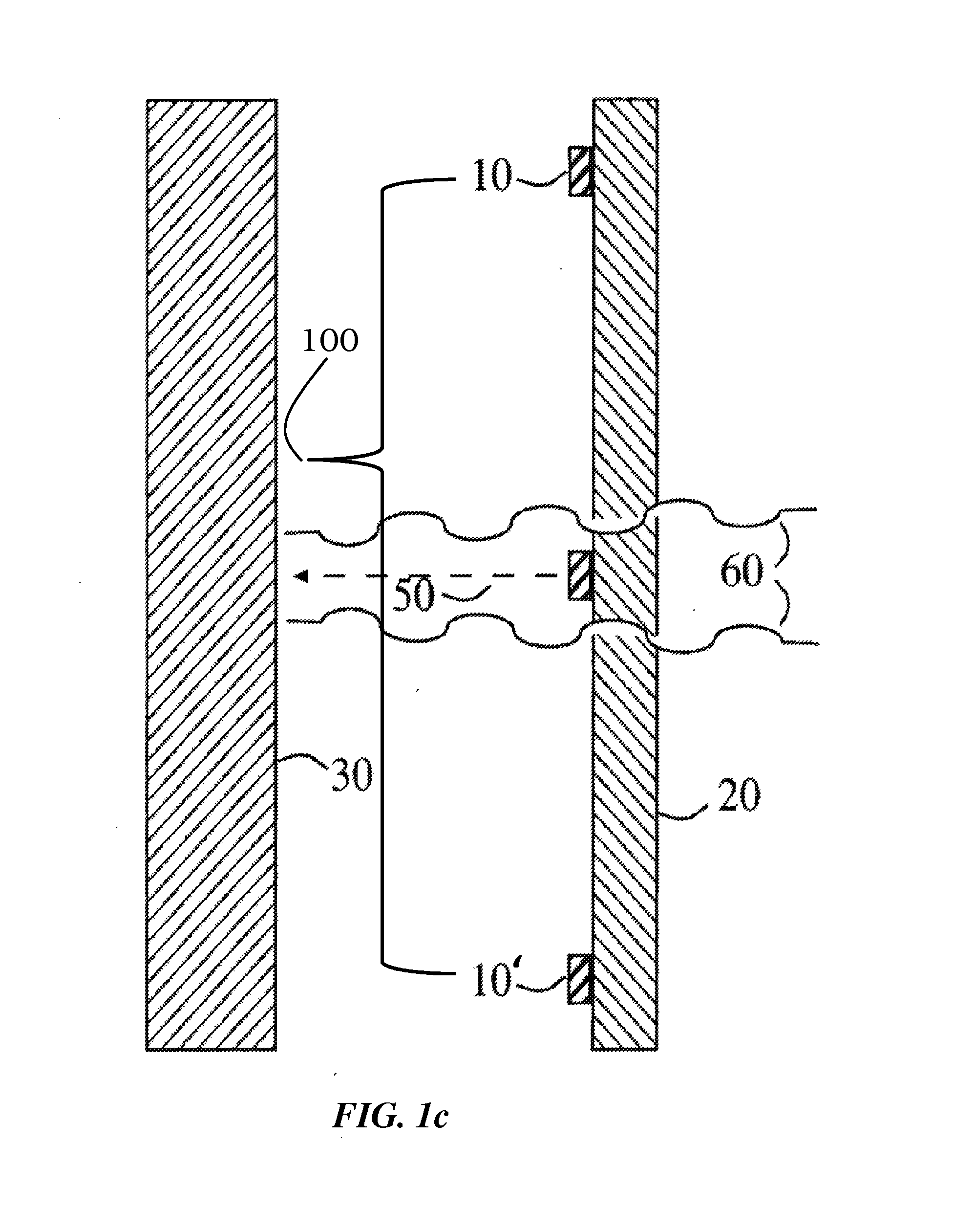
[0034]Although the following detailed description delineates specific attributes of the invention and describes specific designs and fabrication procedures, those skilled in the arts of microfabrication or radiation source production will realize that many variations and alterations in the fabrication details and the basic structures are possible without departing from the generality of the processes and structures. The most general attributes of the invention relate to the cathode array 100 formed on the exit window of the radiation source across from a metal X-ray target.

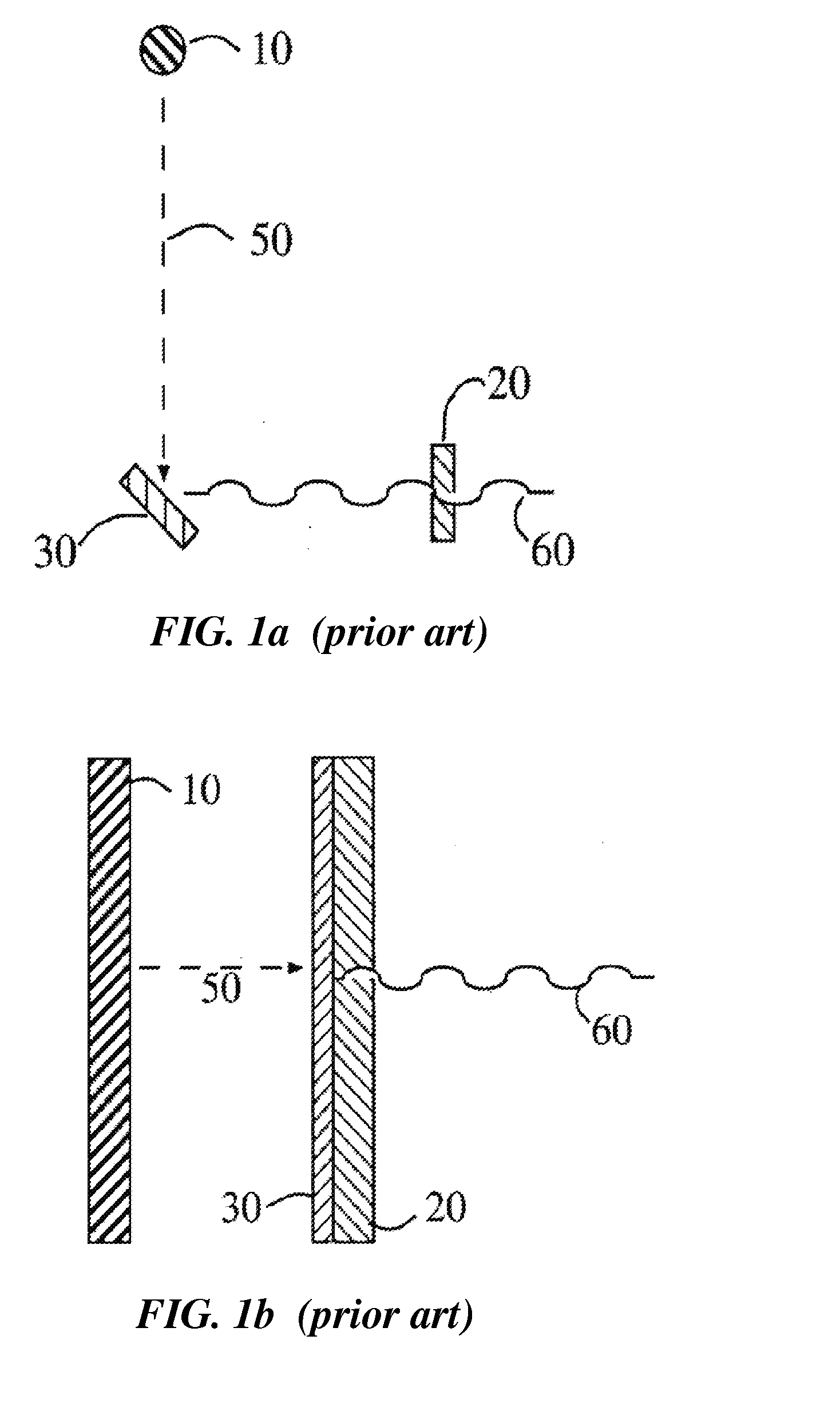
[0035]The general prior art method of producing X-ray flux is shown in FIG. 1a and FIG. 2. A cathode 10, commonly a hot filament cathode operated with an attached heater but more recently a field emission cold cathode, emits an electron beam current 50. An electrical potential established with respect to metal anode 30 directs this current at high velocity across a vacuum to impact the anode, which is disposed at ...


PUM


Abstract

A radiation source which can emit X-ray flux using electron beam currents from a cathode array formed on the window through which the radiation will exit the source. The source can be made in formats which are compact or flat compared with prior art radiation sources. X-ray flux produced by the source can be used for such purposes as radiation imaging, sterilization, decontamination of biohazards or photolithography.

Description

CROSS-REFERENCE TO RELATED APPLICATIONS[0001]This application is a continuation of and claims priority to U.S. application Ser. No. 11 / 355,692, by Mark F. Eaton, entitled “Compact Radiation Source”, filed on Feb. 16, 2006, now abandoned, which is incorporated by reference, as if set forth in its entirety herein.[0002]Parts of this invention were made with Government support under Contract No. FA9451-04-M-0075 awarded by the U.S. Air Force. The Government has certain rights in the invention.FIELD[0003]This disclosure relates in general to the field of radiation production and radiation sources. More particularly, the present disclosure relates to X-ray radiation.BACKGROUND OF THE INVENTION[0004]This invention provides a radiation source which can emit X-ray flux and other forms of radiation producible by an electron beam current. The substance of the invention is the formation of the cathode or cathode array which produces the electron beam current on the window through which the rad...

Claims


Application Information

Patent Timeline
Patent Type & Authority Applications(United States)
IPC IPC(8): H01J35/06
CPCH01J35/06A61L2/082A61L2202/14A61L2202/22A61L2202/23A61L2202/24G21K1/025G21K5/02H01J35/065H01J35/16H01J35/18H01J2235/068H01J2235/081H01J2235/086H01J2235/163H01J2235/18H01J35/064H01J35/112H01J35/116
Inventor EATON, MARK F.
Owner STELLARRAY
Why Eureka
Try Eureka