Compact radiation source

a radiation source and compact technology, applied in the field of compact radiation sources, can solve the problems of common low power efficiency of x-ray tubes, large heat generation of x-rays by electron beam striking the target, and common limitations of cathode x-ray tubes, and achieve the effect of efficient source of x-ray flux generation

Inactive Publication Date: 2007-08-16
STELLAR MICRO DEVICES
View PDF8 Cites 27 Cited by
  • Summary
  • Abstract
  • Description
  • Claims
  • Application Information

AI Technical Summary

Benefits of technology

[0012] The object of this invention is to provide a compact source of useful radiation. A specific object of the invention is to provide a source of X-rays. Another specific object of the invention is to provide a source of UV-C radiation. A further specific object of the invention is to provide a combined source of X-ray and UV-C flux.
[0013] Another object of the invention is to provide a wide-area source of X-ray flux, UV-C flux or the two fluxes in combination.
[0014] Ano

Problems solved by technology

X-ray tubes commonly have low power efficiencies; typically only about 1% of the power used to produce the electron beam current is realized in the X-ray beam energy exiting the tube.
The production of X-rays by the electron beam striking the target also generates a considerable amount of heat, since most of the beam energy is absorbed in the target.
While they offer several improvements, these cold cathode X-ray tubes share the limitations of their hot filament tube predecessors in being essentially point sources of X-rays.
A limitation of this type of X-ray source is that the heat produced in this process can be difficult to manage.
In doing s

Method used


Image

  • Compact radiation source
  • Compact radiation source
  • Compact radiation source

Examples


Embodiment Construction

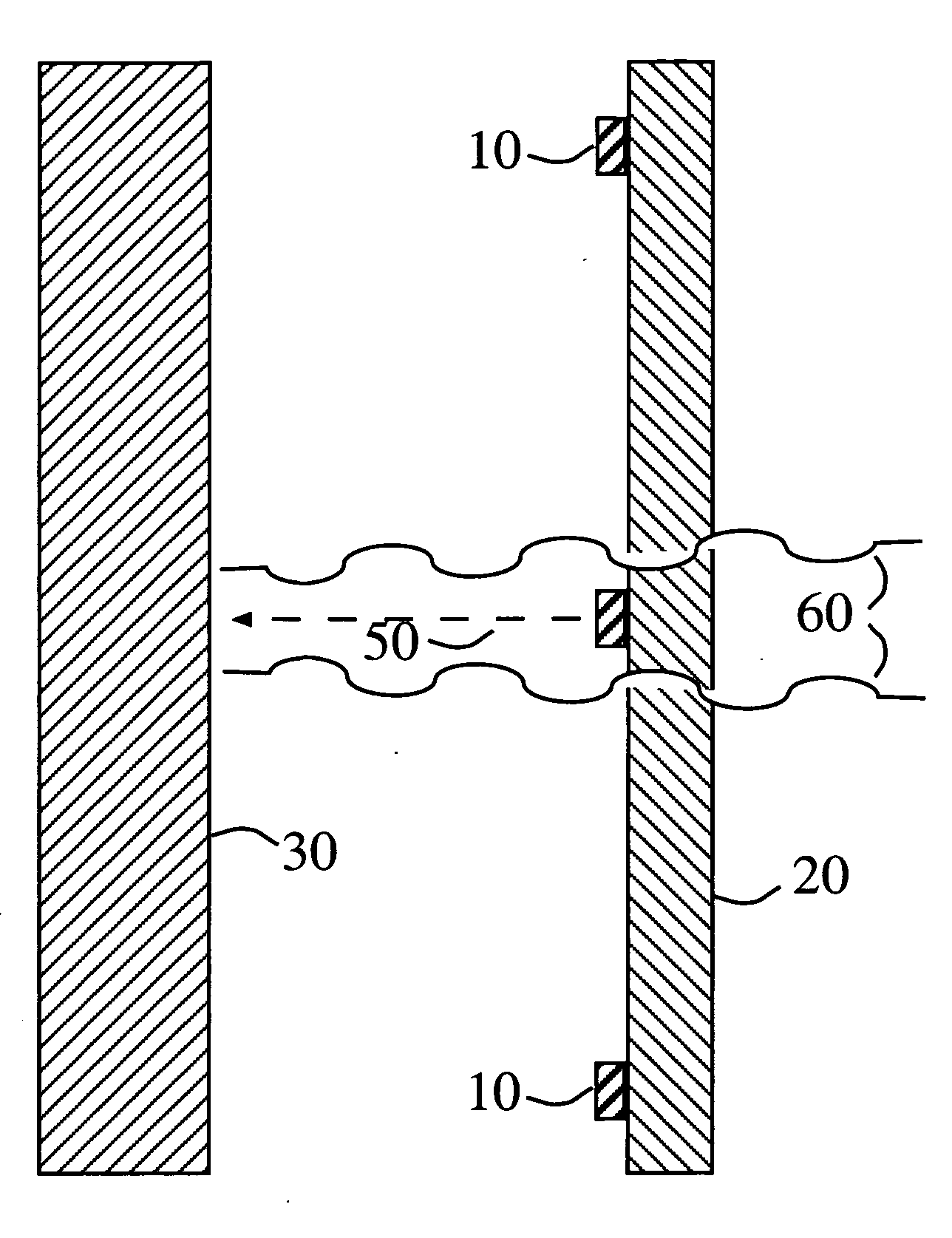
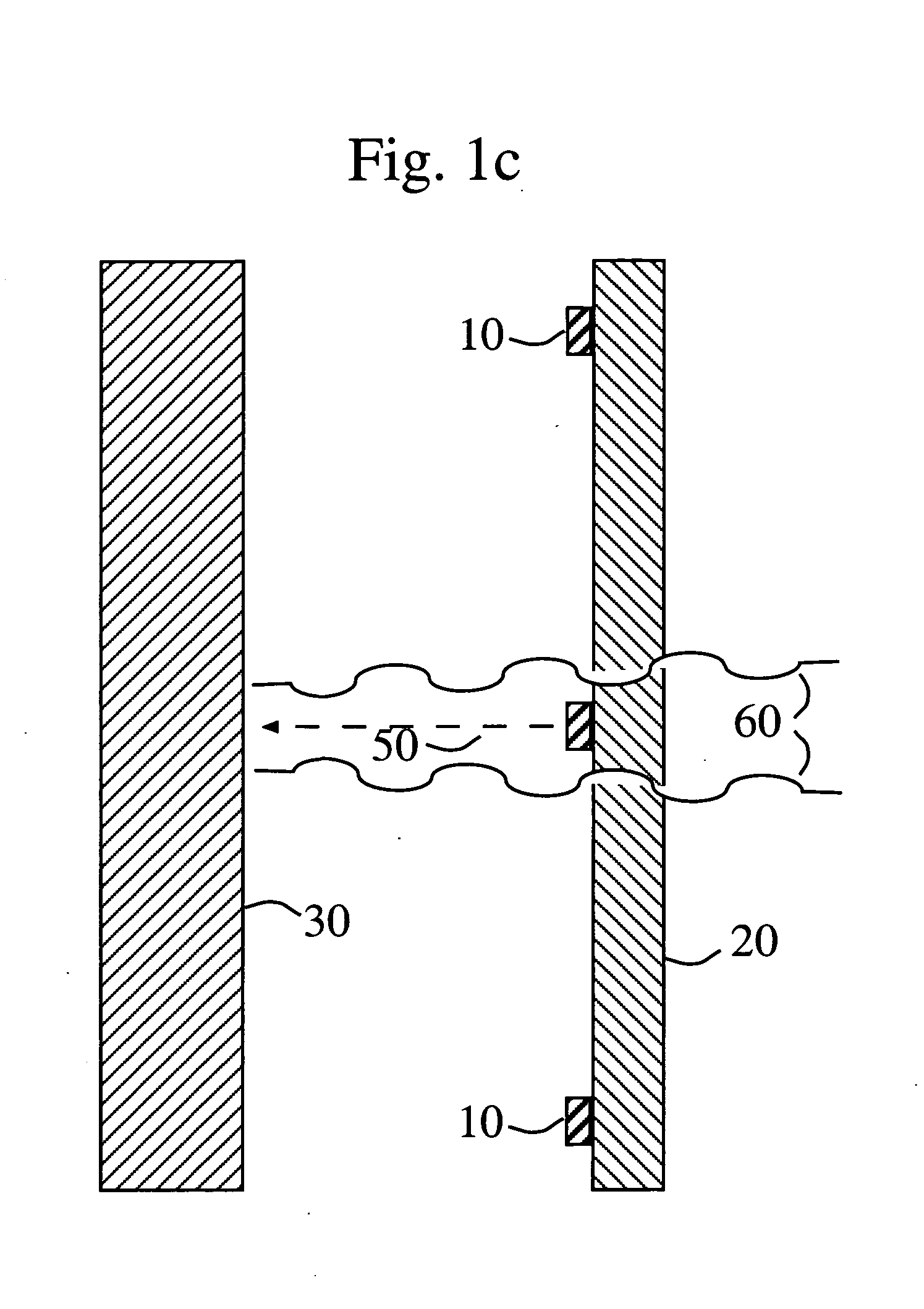
[0046] Although the following detailed description delineates specific attributes of the invention and describes specific designs and fabrication procedures, those skilled in the arts of microfabrication or radiation source production will realize that many variations and alterations in the fabrication details and the basic structures are possible without departing from the generality of the processes and structures. The most general attributes of the invention relate to the cathode or cathode array formed on the exit window of the radiation source. Metal X-ray targets and ultraviolet phosphors can be placed at a number of locations in the source so as to provide emission of either flux individually or both simultaneously and at various operating voltages. Any cathodoluminescent or powder laser phosphor can be used in the source, which can therefore emit light over a number of spectral regions.

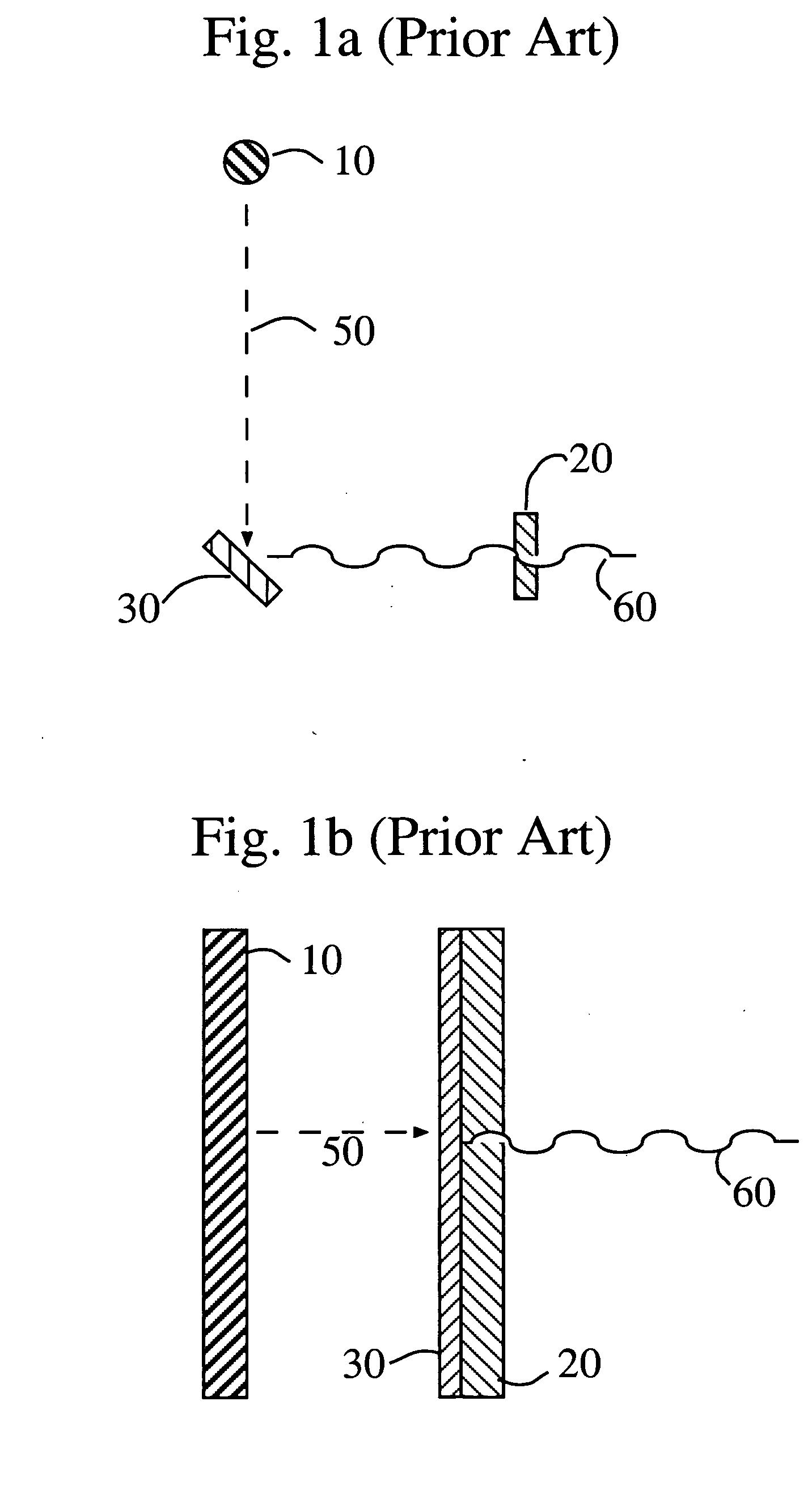
[0047] The general prior art method of producing X-ray flux is shown in FIG. 1a and FIG. ...


PUM


Abstract

A radiation source which can emit X-ray flux, UV-C flux and other forms of radiation uses electron beam current from a cathode array formed on the window through which the radiation will exit the source. The source can be made in formats which are compact or flat compared with prior art radiation sources. X-ray, UV-C and other radiative flux produced by the source can be used for such purposes as radiation imaging, sterilization, decontamination of biohazards, UV curing or photolithography.

Description

STATEMENT REGARDING FEDERALLY FUNDED RESEARCH AND DEVELOPMENT [0001] Parts of this invention were made with Government support under Contract No. FA9451-04-M-0075 awarded by the U.S. Air Force. The Government has certain rights in the invention.DOMESTIC PRIORITY DATA [0002] USPTO Disclosure Document No. 542147, Mark Eaton, Flat UV / X-ray Decontamination Modules, Nov. 17, 2003 BACKGROUND OF THE INVENTION [0003] This invention provides a radiation source which can emit X-ray flux, UV-C flux and other forms of radiation producible by an electron beam current. The substance of the invention is the formation of the cathode or cathode array which produces the electron beam current on the window through which the radiation will exit the source. The radiation source disclosed herein can be made in formats which are compact or flat as compared with prior art radiation sources. X-ray, UV-C and other radiative fluxes produced by the invention can be used for such purposes as radiation imaging, ...

Claims


Application Information

Patent Timeline
IPC IPC(8): H01J35/08
CPCH01J35/065H01J35/08H01J35/14H01J2235/087H01J2235/068H01J2235/081H01J35/16H01J35/112H01J35/116
Inventor EATON, MARK F.KARPOV, LEONID D.
Owner STELLAR MICRO DEVICES
Why Eureka
Try Eureka