
X-Ray Dose Reduction by Controlled Shutter Speed

Inactive Publication Date: 2013-10-17
DEUT MEIR
View PDF6 Cites 22 Cited by
  • Summary
  • Abstract
  • Description
  • Claims
  • Application Information

AI Technical Summary

Benefits of technology

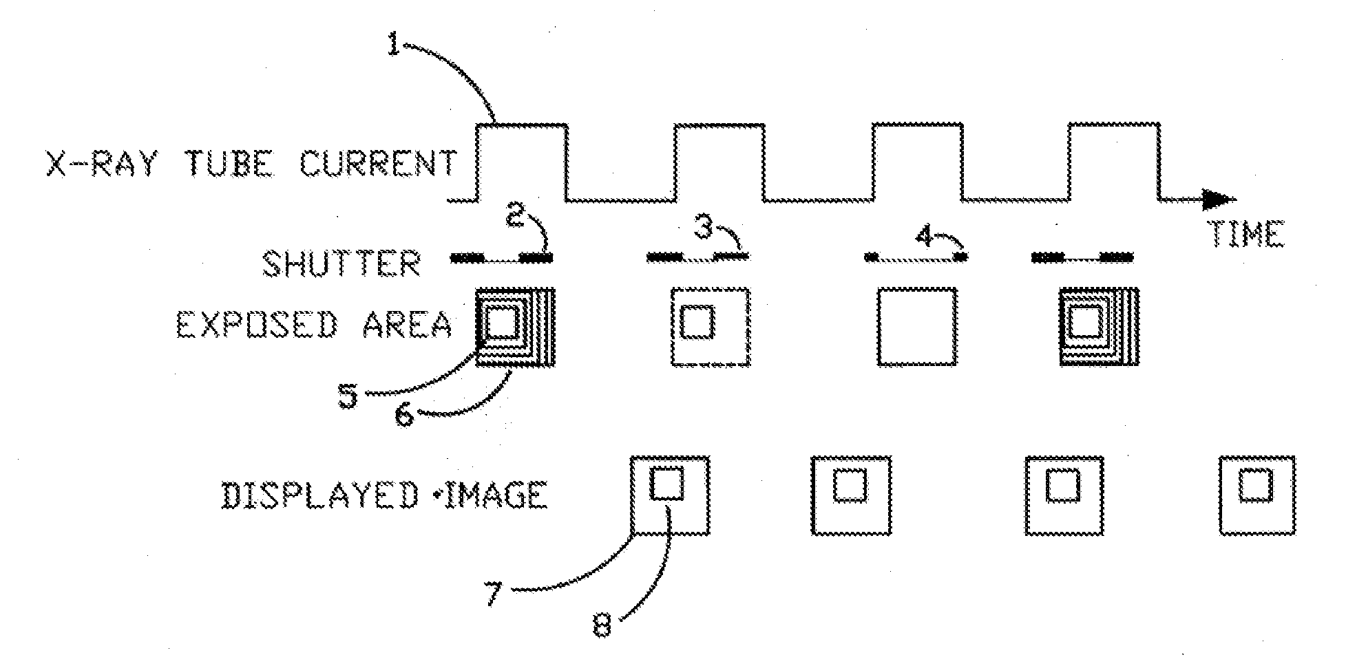
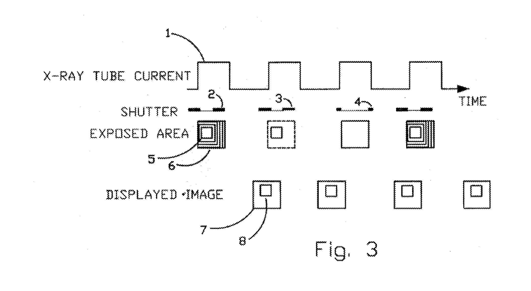
The patent describes a device called a fast moving X-Ray shutter that has four blades that can be controlled independently. The device has a special area of interest (ROI) that is exposed to the X-Ray dose and is exposed at the machine's X-Ray pulse frame rate. The device can automatically control the ROI based on image content using computer vision techniques. The blades also retract at a controlled speed, exposing the area outside the ROI to a lower, non-uniform, exposure. This non-uniformity is then dynamically corrected by a look-up table. The resulting image is a seamless combination of the ROI image and the corrected background image. The image has slightly lower resolution outside the ROI but better resolution in the ROI because of reduced scattering.

Problems solved by technology

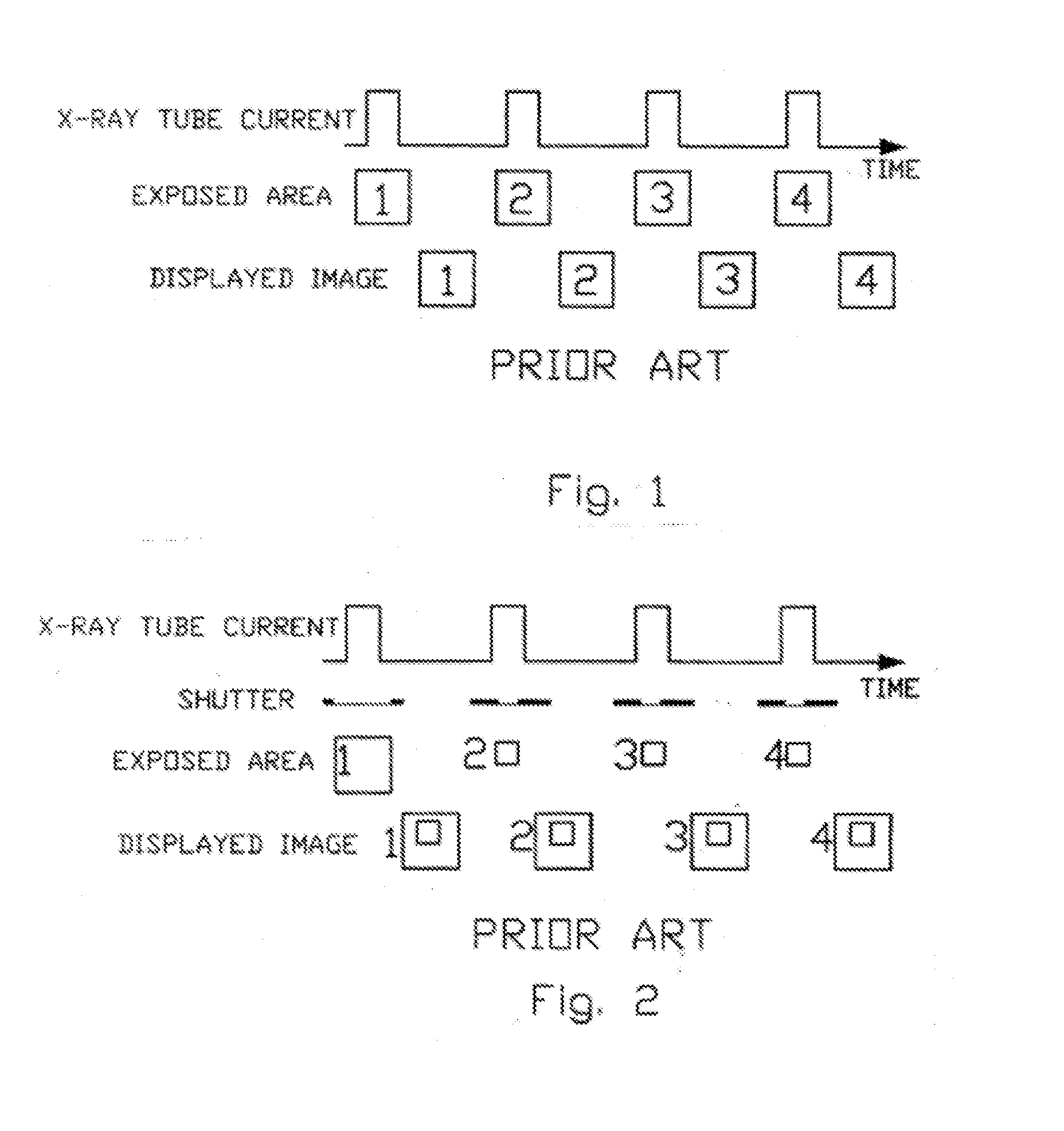
We teach away from this example by allowing the exposure profile to match a varying region of interest using moving shutter blades, which result in a non-uniform exposure profile that can by dynamically adapted to suit the user's preference.

Method used


Image

  • X-Ray Dose Reduction by Controlled Shutter Speed
  • X-Ray Dose Reduction by Controlled Shutter Speed
  • X-Ray Dose Reduction by Controlled Shutter Speed

Examples


Embodiment Construction

[0016]This application is an improvement on U.S. Pat. No. 7,983,391 which is hereby incorporated by reference in its entirety. The improvement allows a use of a shutter controlled ROI to be applied to procedure having fast moving body organs outside the ROI, such as the beating heart during cardiac interventions or when a varying x-ray exposure profile is required. The area outside the ROI is imaged at a lower exposure dose, achieved by using shorter exposure time. Exposure outside the ROI could be different at every location depending on the blade retraction profile. Reducing the dose will reduce the image quality, but the area outside the ROI is of lesser importance to the physician performing the procedure. It was found that even a 10× reduction in the X-Ray dose outside the ROI produces acceptable image. The part of the image inside the ROI actually improved when the ROI is reduced because of reduced X-Ray scattering. We performed an initial experiment to validate this assumptio...


PUM


Abstract

A fast moving X-Ray shutter has four independently controlled blades defining a Region of Interest (ROI). The ROI area receives the normal X-Ray dose and is exposed at the machine's X-ray pulse frame rate. The ROI can be automatically controlled based on image contents using computer vision techniques. Periodically the shutter blades retract at a controlled speed, exposing the area outside the ROI to a lower, non-uniform, exposure. The non-uniformity in this background exposure is dynamically corrected by a look-up table. The displayed image is a seamless combination of the ROI image and the corrected background image. The displayed image has slightly lower resolution outside the ROI but better resolution (as compared to standard fluoroscopy practices) in the ROI because of reduced scattering.

Description

FIELD OF THE INVENTION[0001]The invention relates to the medical field and in particular to the art of continuous X-Ray procedures such as fluoroscopy.BACKGROUND OF THE INVENTION[0002]The increased use of minimally invasive surgery caused an increase in the use of fluoroscopy, exposing the patients, doctors and support staff to ever increasing amounts of radiation.[0003]A typical fluoroscopy unit includes a frame holding the X-Ray source and detector, a patient on a bed and a workstation. The units are known as “C-arm” units because of the C-shaped frame. Existing fluoroscopy systems expose a certain field-of-view (FOV) defined by setting the collimator blades. This operation is sometimes referred to as “coning” (setting the aperture cone). The physician performing the fluoroscopy is usually interested in a smaller region-of-interest (ROI) within the FOV, however the larger image is required for orientation and periodic monitoring. Modern fluoroscopy machines use flat panel detector...

Claims


Application Information

Patent Timeline
IPC IPC(8): G21K1/04
CPCG21K1/04G21K1/043A61B6/06A61B6/487A61B6/542A61B6/545
Inventor DEUTSCH, MEIR
Owner DEUT MEIR
Learn More