Layer furnace system and method for operating the layer furnace system

a technology of layer furnace and layer furnace, which is applied in the direction of furnace components, lighting and heating apparatus, chemical process pressure vessels, etc., can solve the problems of wear or malfunction of such furnace systems, and the limited access to the furnace located there behind is possible, so as to achieve time and cost effective and energy saving

Inactive Publication Date: 2013-10-17
BENTELER AUTOMOBILTECHNIK GMBH
View PDF61 Cites 11 Cited by
  • Summary
  • Abstract
  • Description
  • Claims
  • Application Information

AI Technical Summary

Benefits of technology

[0043]The temporal opening variants offer the advantages that a maximal range of movement over twice a furnace door distance is utilized and optimally adjusted to the process time of the thermal treatment. The furnace can thus be loaded continuously in correspondence with the respective opened heating levels and thermally treated sheets can be removed from the furnace. At the same time, the linear drive is used in a time and cost effective and energy saving manner. In this way, the linear drive does not have to be moved over the entire length of the furnace in order to selectively actuate a furnace door, but it can successively work off the furnace doors of the individual heating levels.

Problems solved by technology

On one hand, such a furnace lid has the disadvantage that the distance of the individual heating levels to each other is in part defined by the lid mechanics, and on the other hand that a corresponding mechanics has to take different thermal expansions into account with regard to the pivot axis in order to ensure a proper functioning in different heating stages of the furnace.
Even then, wear or malfunctions sometimes occur in such furnace systems during operation.
Common to both previously mentioned lid systems in the aforementioned furnace door systems is that in the case of maintenance or repair, only limited access to the furnace located there behind is possible.

Method used


Image

  • Layer furnace system and method for operating the layer furnace system
  • Layer furnace system and method for operating the layer furnace system
  • Layer furnace system and method for operating the layer furnace system

Examples


Embodiment Construction

[0052]Throughout all the figures, same or corresponding elements may generally be indicated by same reference numerals. These depicted embodiments are to be understood as illustrative of the invention and not as limiting in any way. It should also be understood that the figures are not necessarily to scale and that the embodiments are sometimes illustrated by graphic symbols, phantom lines, diagrammatic representations and fragmentary views. In certain instances, details which are not necessary for an understanding of the present invention or which render other details difficult to perceive may have been omitted.

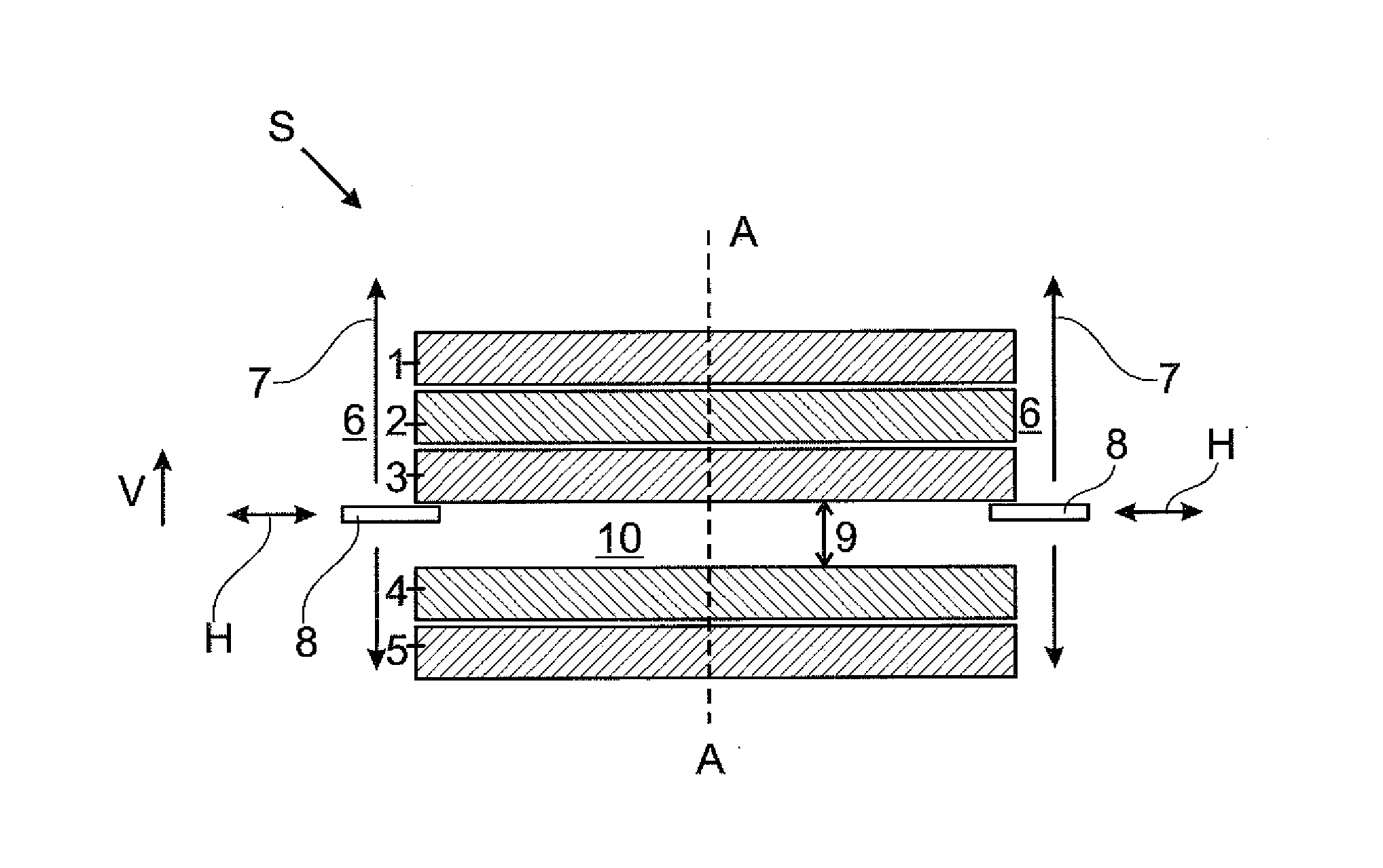
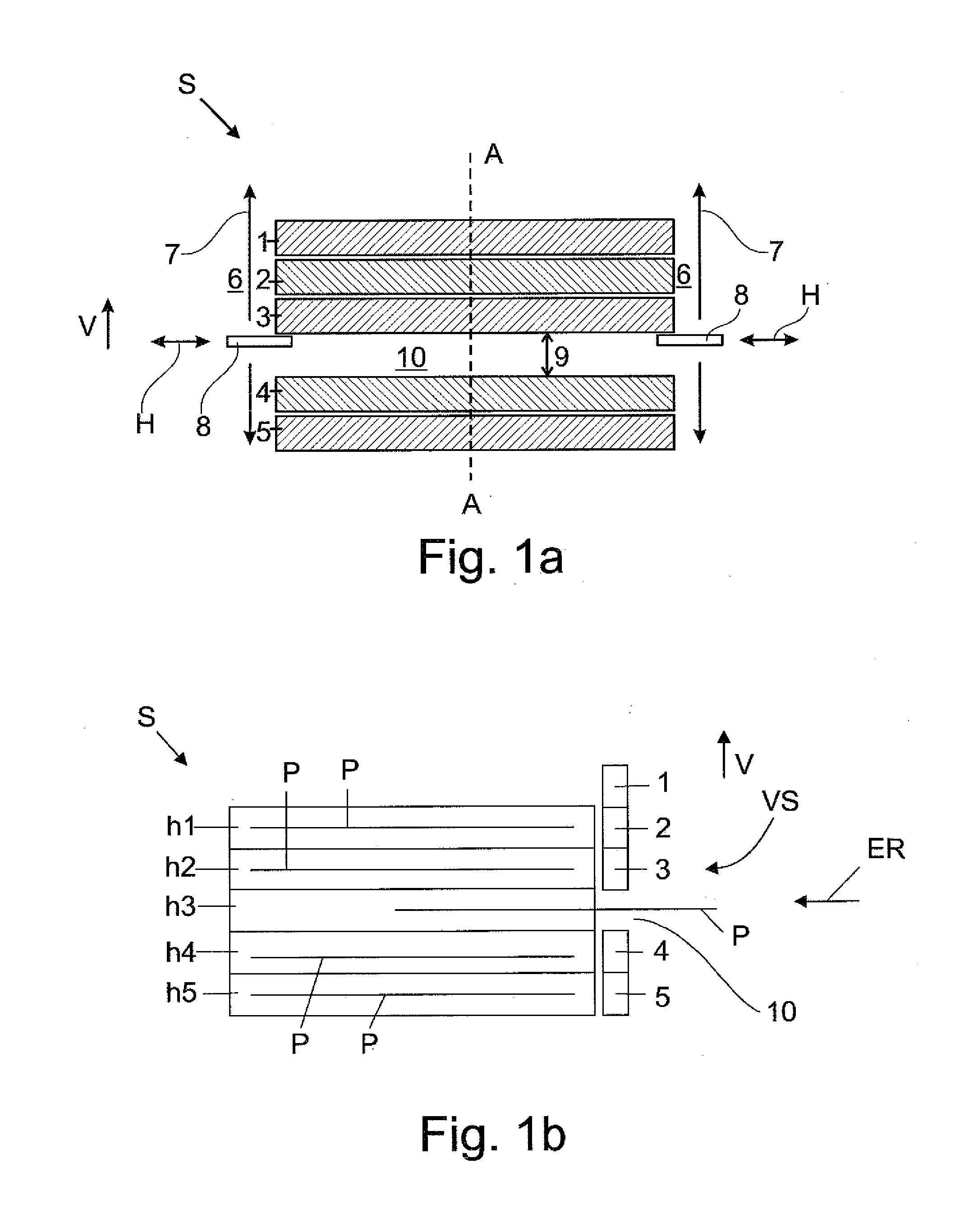
[0053]Turning now to the drawing, and in particular to FIG. 1a, there are shown five furnace doors 1, 2, 3, 4, 5, stacked on top of one another which can be shifted in vertical direction V. FIG. 1b shows a cross sectional side view of the layer furnace system taken along the cut line A-A of FIG. 1a. According to FIG. 1b, five heating levels h1 to h5 which are stacked on to o...


PUM

PropertyMeasurementUnit
sizeaaaaaaaaaa
temperaturesaaaaaaaaaa
widthaaaaaaaaaa

Abstract

A layer furnace system for thermal treatment of metal components includes multiple heating levels which arranged on top of each other in vertical direction, and at least one heat source, wherein flat metal components, in particular metal sheets can be inserted into the heat levels and at last one heating level can be closed by a furnace door, wherein the furnace door is can be displaced in vertical direction for opening and closing the heat level located there behind. The present invention also relates to a method for operating the layer furnace system.

Description

CROSS-REFERENCES TO RELATED APPLICATIONS[0001]This application claims the priority of German Patent Application, Serial No. 10 2012 103 275.0, filed Apr. 16, 2012, pursuant to 35 U.S.C. 119(a)-(d), the content(s) of which is / are incorporated herein by reference in its entirety as if fully set forth herein.BACKGROUND OF THE INVENTION[0002]The present invention relates to a layer furnace system and to a method for operating the layer furnace system.[0003]The following discussion of related art is provided to assist the reader in understanding the advantages of the invention, and is not to be construed as an admission that this related art is prior art to this invention.[0004]From the state of the art, layer furnace systems are known, for heating in particular steel plates. For this, steel plates i.e., flat metal components which can have dimensions of a few square centimeters up to several square meters, are introduced into the layer furnace system.[0005]Such a layer furnace system is...

Claims


Application Information

Patent Timeline
Patent Type & Authority Applications(United States)
IPC IPC(8): F27D7/00
CPCF27D7/00F27B9/024F27B9/025F27B9/029F27D1/1858C21D9/005C21D9/46
Inventor DVORAK, BOREKKOUT, RADOVAN
Owner BENTELER AUTOMOBILTECHNIK GMBH
Why Eureka
Try Eureka